
Protective cover for constant-velocity universal joint

A technology of constant velocity universal joint and protective cover, which is applied in the field of protective cover and can solve problems such as biting

Inactive Publication Date: 2008-09-03
FUKOKU CO LTD
View PDF3 Cites 0 Cited by
  • Summary
  • Abstract
  • Description
  • Claims
  • Application Information

AI Technical Summary

Problems solved by technology

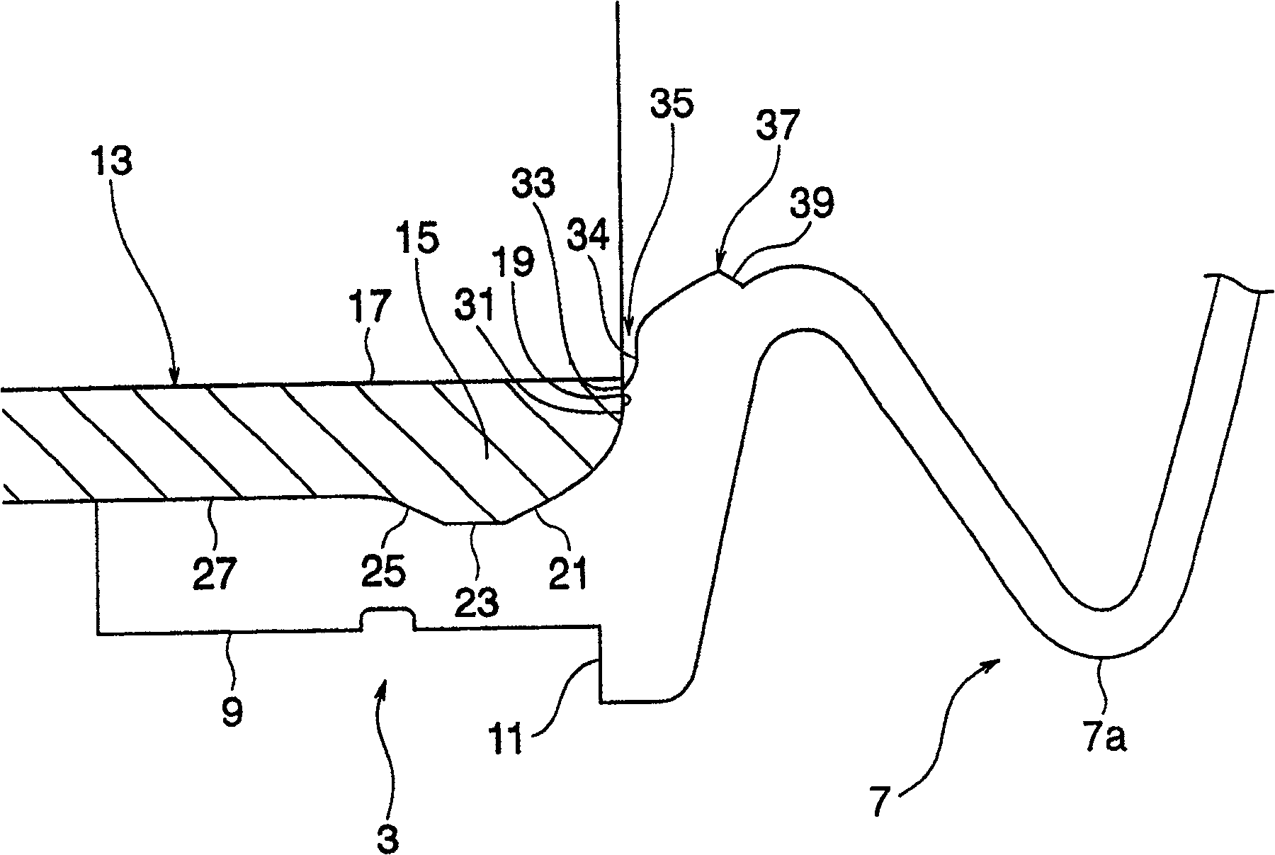
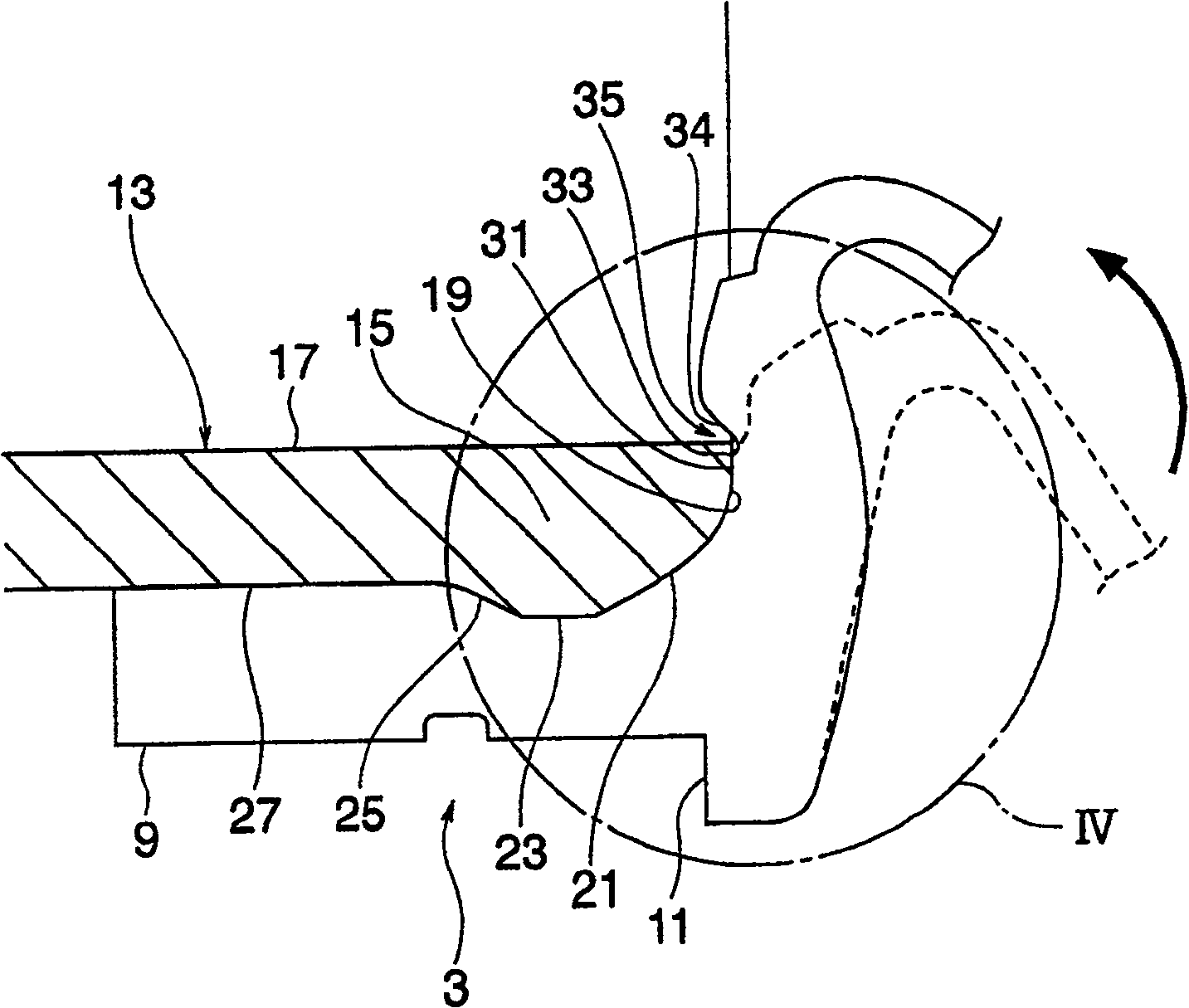
[0004] However, in the boot for the constant velocity joint described above, when the boot for the constant velocity joint is bent accompanying the suspension or bending stroke of the drive shaft caused by the steering operation, the same as the constant velocity joint The inner circumferential surface of the boot, which the tip of the joint housing is in contact with, is pressed against the tip of the CV joint housing, in some cases so-called "biting" occurs

Method used


Image

  • Protective cover for constant-velocity universal joint
  • Protective cover for constant-velocity universal joint
  • Protective cover for constant-velocity universal joint

Examples


Embodiment Construction

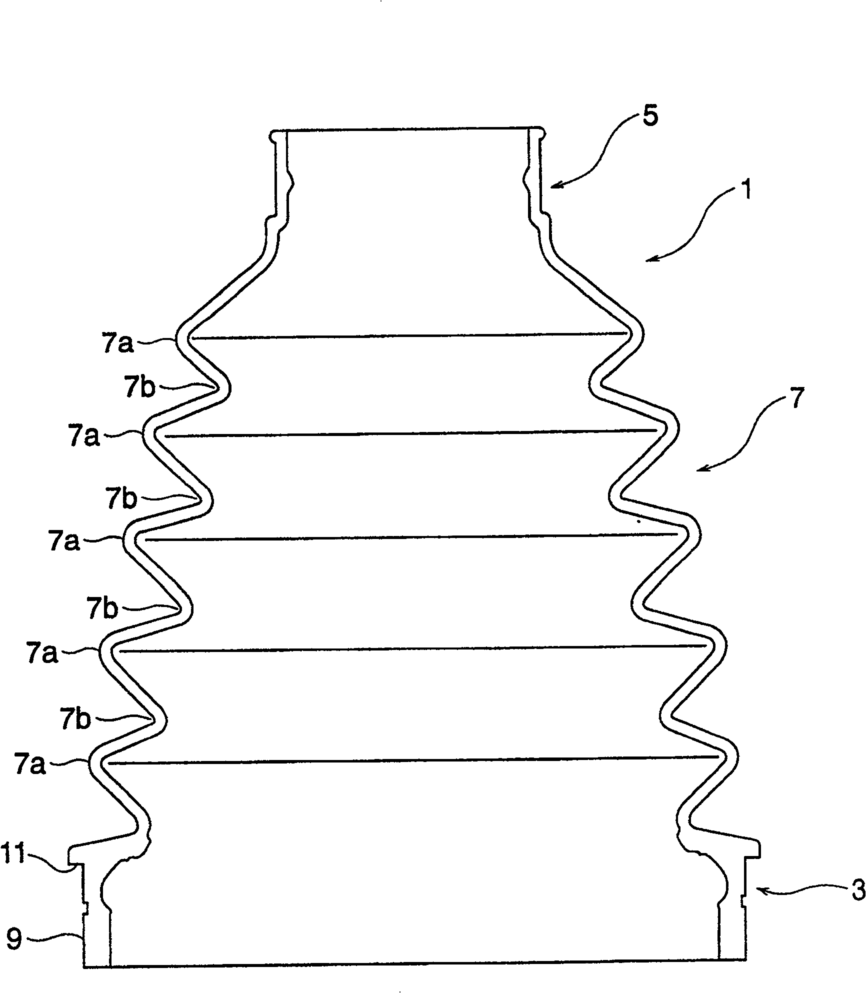
[0013] An embodiment of a protective cover for a constant velocity joint applied to the present invention will be described below. figure 1 A front view showing an appearance of a boot for a constant velocity joint according to an embodiment of the present invention. Such as figure 1 As shown in , the protective cover 1 is made cylindrical and has a large end portion 3 fixed to the side of the constant velocity joint, and a shaft fixed to the drive shaft connected to the constant velocity joint. The small end part 5 of the side. Furthermore, a flexible and structurally bendable bellows 7 is formed between the large end portion 3 and the small end portion 5 . It should be noted that in the embodiment of the present invention, the protective cover 1 is formed of a resin having elasticity, such as a thermoplastic polyester-based elastomer.

[0014] The bellows 7 is composed of repeatedly arranged convex portions 7a and concave portions 7b extending circumferentially in the dir...


PUM


Abstract

The present invention discloses a kind of protecting hood for constant speed gimbal. The protecting hood is so constructed that its inner surface will not be bitten by the edge part of the constant speed gimbal. The protecting hood for constant speed gimbal includes one large end part for the casing of the constant speed gimbal to be inserted in, one small end part for the shaft part connected to the constant speed gimbal to be inserted in, and one bellows in between. The large end part has one plane part toward the pointed end of the constant speed gimbal and formed through notching one part of the casing end.

Description

technical field [0001] The invention relates to a boot for the protection of a constant velocity joint, for example, on a drive shaft (force transmission shaft) or similar, which transmits force from a differential gear of a car to a bushing, In particular, it is prevented from being damaged by the sharp edge of the end face of the constant velocity joint housing. Background technique [0002] Constant velocity joints are used for opposite end sections, for example, for drive shafts of automobiles. In addition, a flexible protective cover is attached in such a manner that it covers the curved portion of the constant velocity joint for sealing the grease lubricating the constant velocity joint, and prevents foreign substances such as dust and water from coming from the outside. Enter. The large and small end portions of the protective cover utilize fastening means such as straps (see, for example, Japanese Patent Application Laid-open No. 2002-39208, page 1 and appended fi...

Claims


Application Information

Patent Timeline
Patent Type & Authority Patents(China)
IPC IPC(8): F16D3/84F16D3/16
Inventor 末冈一彦高田康二
Owner FUKOKU CO LTD
Learn More