
Technique for removing CO2 from flue-gas

A technology of carbon dioxide and process methods, applied in chemical instruments and methods, separation methods, chemical separation, etc., can solve problems such as low partial pressure of carbon dioxide, explosion, slow reaction rate, etc., to increase solubility, improve removal efficiency, and avoid The effect of clogging

Inactive Publication Date: 2008-07-23
陈明功
View PDF4 Cites 0 Cited by
  • Summary
  • Abstract
  • Description
  • Claims
  • Application Information

AI Technical Summary

Problems solved by technology

There are also some reports on the removal of carbon dioxide in flue gas by ammonia absorption method: Bai H. et al. used semi-continuous ammonia water bubbling to absorb carbon dioxide simulated gas, Yeh J.T. et al studied the effect of other components in flue gas on ammonia water bubbling to absorb carbon Due to the low concentration of carbon dioxide and the difficulty of dissolving carbon dioxide under normal pressure, the reaction time of this method is long and the absorption efficiency is low.
In 2003, James W.Lee et al. mixed ammonia and water vapor into the simulated flue gas to react with carbon dioxide. Due to the extremely fast gas phase reaction rate, it was easy to generate ammonium carbamate to block the pipeline. NH 4 HCO 3 The yield is low; the flue gas contains a certain concentration of oxygen, and there is a danger of explosion
Due to the large flue gas flow rate of power plant boilers, low carbon dioxide partial pressure, high temperature, and a large amount of inert gas N 2 , complex composition and other characteristics, so that some of the above-mentioned ammonia water absorption methods have the disadvantages of low carbon dioxide removal efficiency and slow reaction rate.

Method used


Image

  • Technique for removing CO2 from flue-gas
  • Technique for removing CO2 from flue-gas

Examples


Embodiment 1

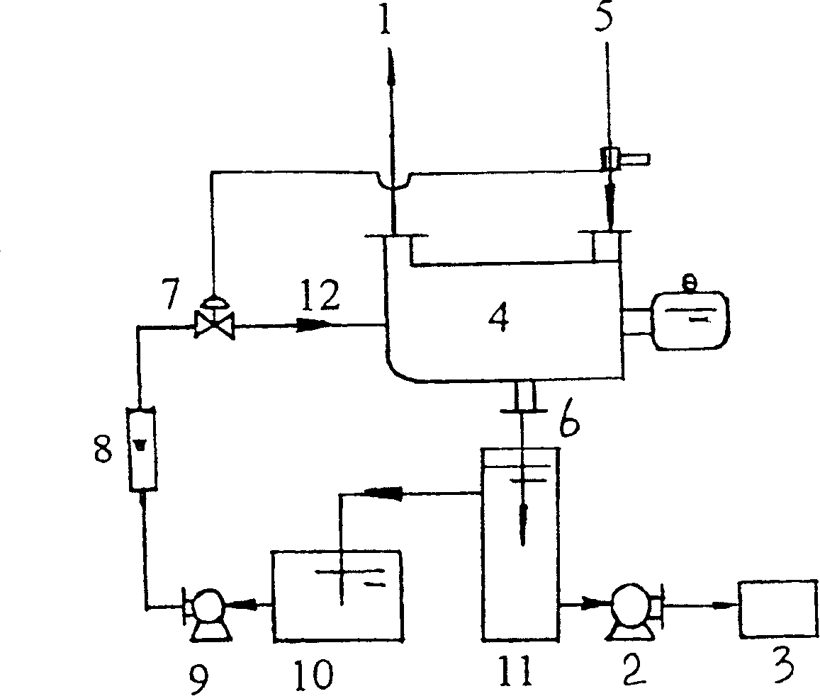
[0025] A process for removing carbon dioxide in flue gas comprises the following process steps:

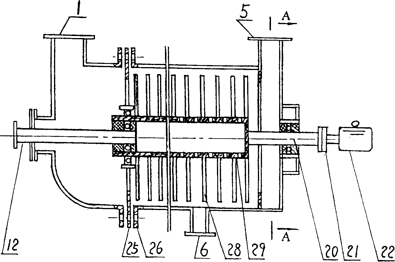
[0026] A, the flue gas containing carbon dioxide is sent into the smoke inlet end of the absorption reactor 4 along the tangential direction, so that it flows from the smoke inlet 5 end to the gas outlet 1 end;

[0027] B. Simultaneously, spray ammonia water with a concentration of 8% from the through hole on the central shaft in the axial middle, and spray it into the absorption reactor 4 from the inside to the outside in the radial direction, so that the gas and liquid two-phase cross-flow contact reaction;

[0028] C, the liquid after the reaction flows into the airtight intermediate storage tank 11 from the drain port 6 at the bottom of the absorption reactor 4, and the solid matter generated is deposited at the bottom of the intermediate storage tank 11, and the supernatant of the intermediate storage tank 11 overflows into the ammonia water tank 10 ;

[0029] D, add an appr...

Embodiment 2

[0038] Adjust the ammonia concentration in the ammonia tank 10 to be 10%. Other technological process is with embodiment 1.

Embodiment 3

[0040] Adjust the ammonia concentration in the ammonia tank 10 to be 16%, and the other processes are the same as in Example 1.


PUM


Abstract

A process for removing the CO2 from the flue fume of power plant includes such steps as introducing the flue fume containing CO2 to an absorptive reactor, axially spraying 8-16% ammonia water into the absorptive reactor, gas-liquid cross-flow contact reaction, and exhausting CO2 gas. The removal rate of CO2 is 86-94%.

Description

technical field [0001] The invention relates to a process for removing carbon dioxide in flue gas of a power plant. Background technique [0002] Carbon dioxide is the main greenhouse gas, which is produced by the combustion of fossil energy. Global warming will bring unprecedented disasters to human beings. Therefore, it is urgent to remove carbon dioxide in the flue gas of coal-fired boilers in power plants. [0003] The control of the greenhouse gas carbon dioxide has been paid attention all over the world. The research methods reported so far include absorption method, adsorption method, freezing method, membrane separation method, biological method and so on. The main way of the above methods is to separate, concentrate and compress the carbon dioxide in the flue gas, and then inject it into the deep sea for storage, or inject it into the underground storage of oil fields and coal mines. However, when there are natural disasters such as earthquakes and tsunamis, the ca...

Claims


Application Information

Patent Timeline
Patent Type & Authority Patents(China)
IPC IPC(8): B01D53/14B01D53/62
CPCY02C10/04Y02C10/06Y02A50/20Y02C20/40
Inventor 陈明功张洪流董众兵
Owner 陈明功
Learn More