
Temperature compensating crystal oscillator structure and its manufacturing method

A technology of temperature compensation and manufacturing method, applied in the direction of power oscillator, electrical components, etc., can solve the problems of customer interference, difficulty, small distance, etc., and achieve the effect of low cost and easy production

Inactive Publication Date: 2008-05-21
DELTA ELECTRONICS INC
View PDF4 Cites 0 Cited by
  • Summary
  • Abstract
  • Description
  • Claims
  • Application Information

AI Technical Summary

Problems solved by technology

Although this structure can avoid the influence of volatilized resin or soldering residue on the resonant element when the integrated circuit is packaged like the first structure, it needs to use another ceramic container to carry the integrated circuit. The container is made of multi-layer ceramics through low-temperature co-firing process, only a few companies can mass-produce, so the cost is very high
[0006] On the other hand, in the above two structures, there are several external electrodes used for program input to the integrated circuit on the final product. After the input is completed, these electrodes have no other purpose, but in the process of use, these useless Electrodes will cause interference to customers. For example, it is necessary to consider whether there is a possibility of short circuit with other circuits, which makes product design more complicated.
On the other hand, as the structure of temperature-compensated oscillators becomes smaller and smaller, the distance between several external electrodes becomes smaller and smaller, so it becomes more and more difficult to keep these external electrodes in good contact with the control signal.

Method used


Image

  • Temperature compensating crystal oscillator structure and its manufacturing method
  • Temperature compensating crystal oscillator structure and its manufacturing method
  • Temperature compensating crystal oscillator structure and its manufacturing method

Examples


Embodiment Construction

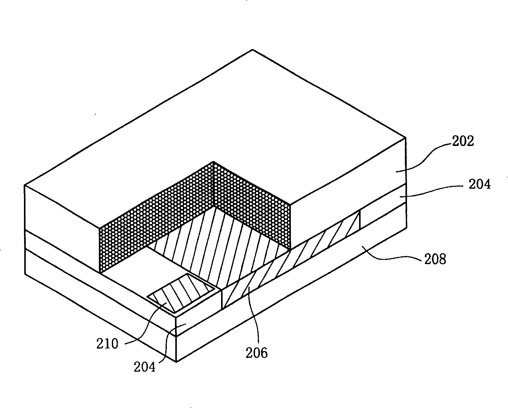
[0024] Without limiting the concept of the present invention and the scope of application, the implementation of the present invention is described below with an embodiment; those of ordinary skill in the art can use it in various applications after understanding the concept of the present invention The temperature-compensated oscillator of the present invention, with the help of the structure of the present invention, can avoid the impact of impurities formed during the bonding process of integrated circuits on the resonant element because it is packaged in a ceramic container at the same time. At the same time, in the structure of the present invention, the integrated circuit is packaged on the printed circuit board without using another ceramic container, so the manufacturing cost can be reduced. Moreover, the structure of the present invention leads the used electrodes out of the structural elements, so that some electrodes with the same signal can be connected together, wh...


PUM


Abstract

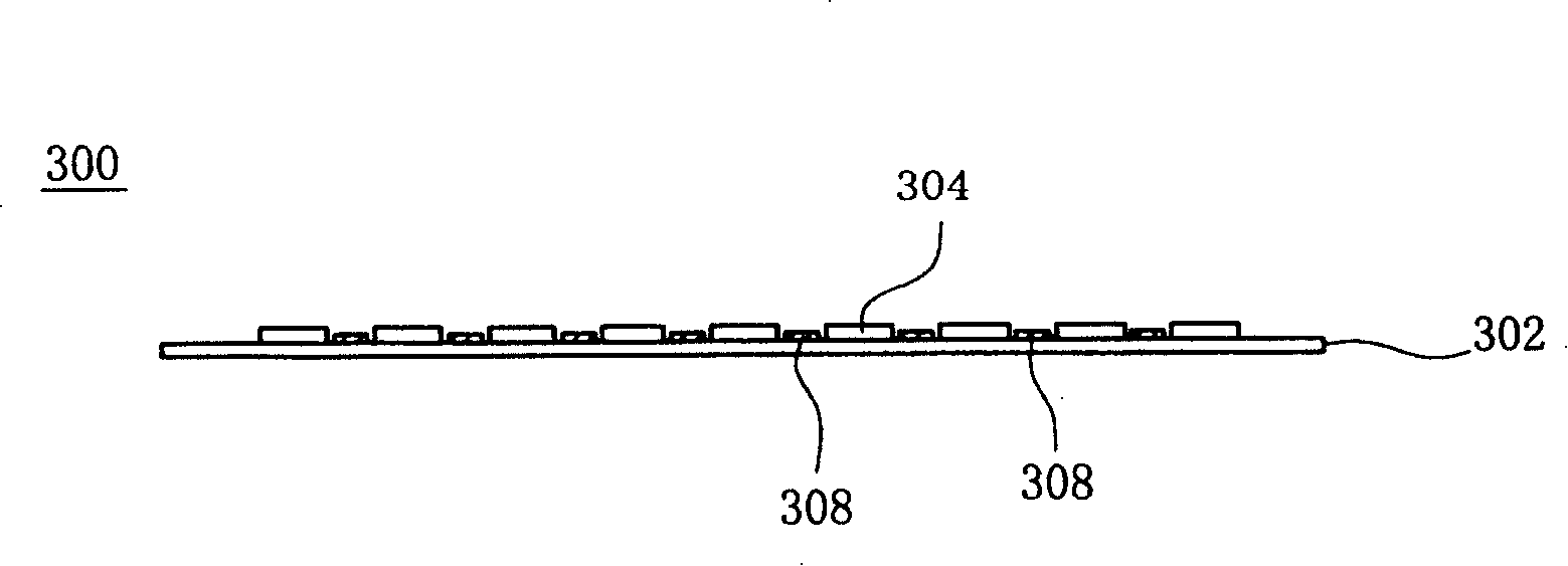
The invention discloses structure for forming temperature compensated crystal oscillator on printing circuit board (PCB). First, several crystal connection plates are arranged on PCB in mode of parallel arrangement. Then, several IC circuits possessing function of temperature compensation are setup between any two adjacent crystal connection plates; and resin is filled for seal. After complete seal, quartz crystal is pasted above each IC, and each piece of quartz crystal is cross connected between two adjacent crystal connection plates so as to cover corresponding IC.

Description

technical field [0001] The present invention relates to a crystal oscillator device and its manufacturing method, in particular to a temperature-compensated crystal oscillator device and its manufacturing method. Background technique [0002] Crystal oscillators are generally used in applications that require a stable output frequency, such as in mobile phones, as a frequency reference source. However, the output frequency of a conventional crystal oscillator varies as a function of the temperature surrounding the oscillator. see figure 1 A graph of oscillation frequency versus ambient temperature is shown for a typical uncompensated quartz crystal. Such as figure 1 As shown, the curve 100 has a shape like a cubic curve, which can be roughly divided into three temperature regions. In the low temperature region (-35°C to about +10°C), the curve has a linear portion with a positive slope and a non-linear region where the slope of the curve changes. In the medium temperatu...

Claims


Application Information

Patent Timeline
Patent Type & Authority Patents(China)
IPC IPC(8): H03B5/04
Inventor 刘贵枝
Owner DELTA ELECTRONICS INC
Learn More