Eureka AIR delivers breakthrough ideas for toughest innovation challenges, trusted by R&D personnel around the world.

Floor brush device of dust collector

A technology of vacuum cleaners and suction ports, applied in the direction of suction nozzles, etc., can solve the problems of affecting the cleaning effect and being unable to continue pumping, and achieve the effect of reducing secondary pollution

Active Publication Date: 2008-04-30
ECOVACS ROBOTICS (SUZHOU ) CO LTD
View PDF9 Cites 0 Cited by
  • Summary
  • Abstract
  • Description
  • Claims
  • Application Information

AI Technical Summary

Problems solved by technology

[0003] However, for wet / dry vacuum cleaners or steam vacuum cleaners, in the process of sucking the liquid on the surface to be cleaned, once the power of the main machine is turned off, the water pumped into the hard pipe cannot continue to be pumped due to the reduced suction force of the vacuum source. into the recycling bin inside the vacuum cleaner
In this way, the liquid in the hard tube will flow back and flow back to the ground along the hard tube, which will affect the cleaning effect

Method used


Image

  • Floor brush device of dust collector
  • Floor brush device of dust collector
  • Floor brush device of dust collector

Examples


Embodiment 1

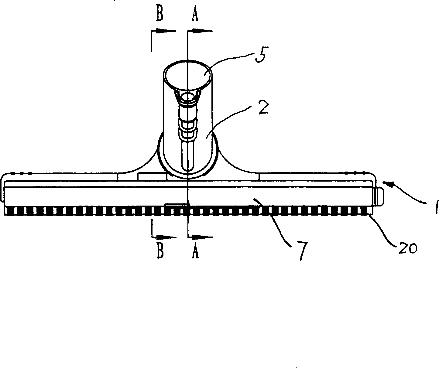
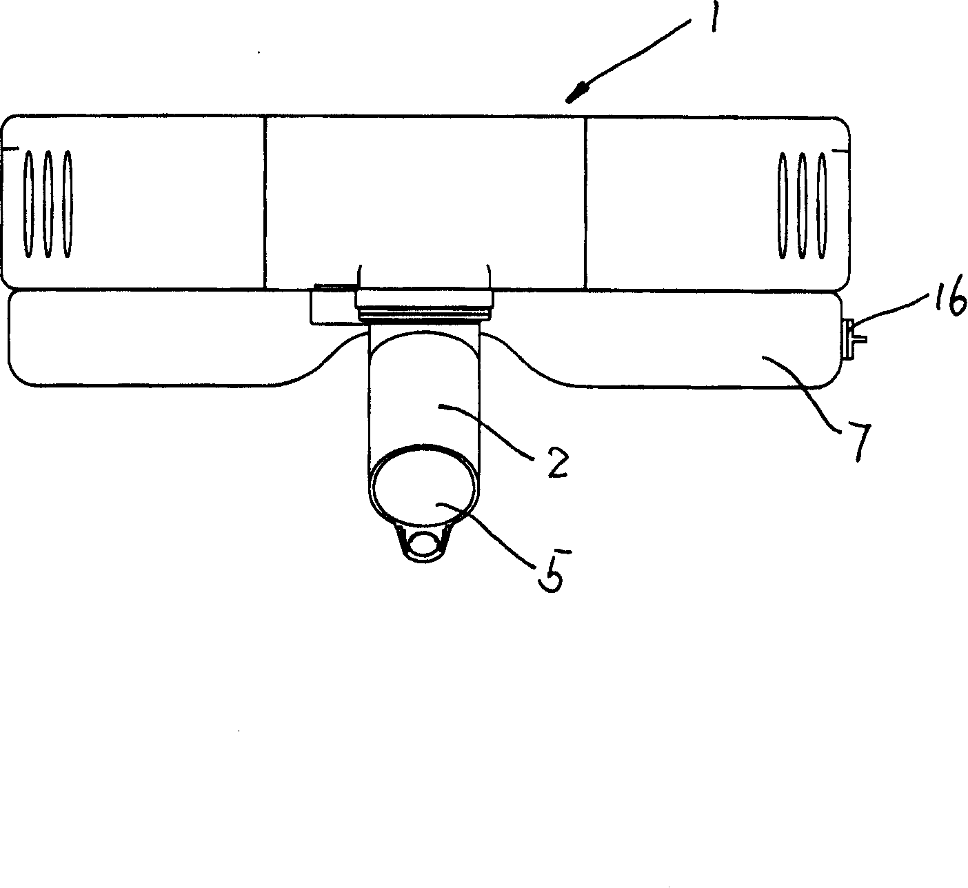
[0022] as attached figure 1 , attached figure 2 , and attached Figure 5 As shown, a floor brush device of a vacuum cleaner includes a floor brush body 1 and a pipe joint 2 arranged on the floor brush body 1 . The ground brush body 1 includes a housing 11 , a bottom plate 6 , and a brush 20 and a roller 21 arranged on the bottom plate 6 . The bottom plate 6 is provided with a suction port 3 . The floor brush body 1 is provided with a dust suction passage 4 inside, and the pipe joint 2 has a lumen 5 inside, and the dust suction port 3 communicates with the lumen 5 through the dust suction passage 4 .

[0023] The ground brush device of the vacuum cleaner also includes a water storage tank 7 . The water storage tank 7 includes an upper cover 18 and a lower box body 17, and the water storage tank 7 is formed by interlocking the upper cover 18 and the lower box body 17. A water inlet 19 is provided on the top of the water storage tank 7 , and a water discharge port 15 is pro...

Embodiment 2

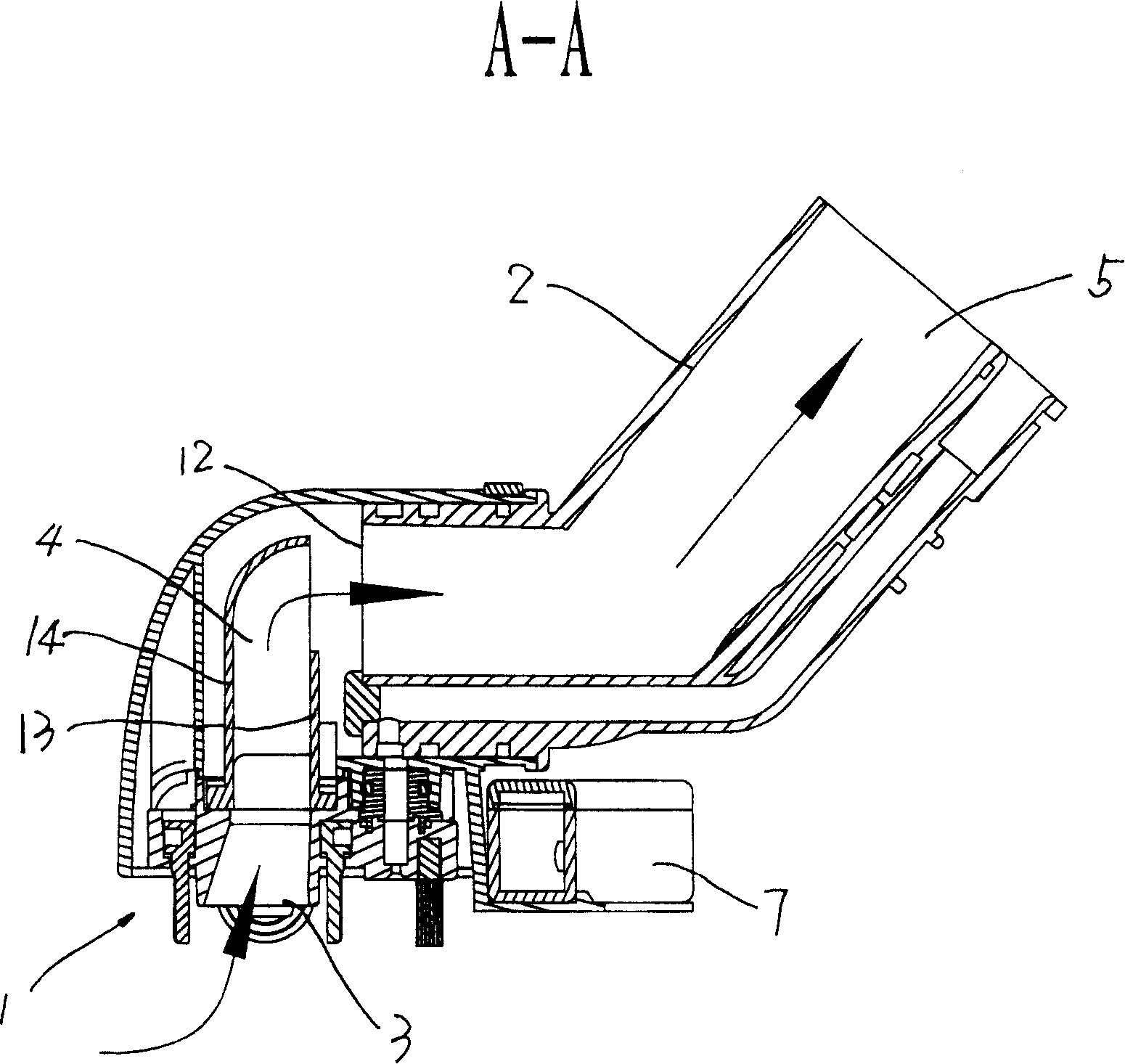
[0029] as attached image 3 As shown, in the normal working state of the vacuum cleaner, the suction airflow generated in the floor brush device of the vacuum cleaner according to the present invention flows as shown by the arrow in the figure. The liquid on the surface to be cleaned enters the suction channel 4 from the suction port 3 along with the suction gas, and enters the interior of the vacuum cleaner through the lumen 5 in the pipe joint 2 .

[0030] as attached Figure 4 And attached Figure 6 As shown, when the power of the vacuum cleaner is turned off, the suction force of the liquid-solid vacuum source in the hard tube of the vacuum cleaner (not shown in the figure) decreases to generate backflow, and the flow direction of the backflow liquid is shown in the direction of the arrow in the figure. The reflux liquid flows back down along the lumen 5 of the pipe joint 2 , is blocked by the reflux baffle 13 , and is collected by the liquid collection tray 9 , and flow...


PUM


Abstract

The invention relates to a ground brush device of vacuum cleaner, which comprise ground brush body and tube joint mounted at the ground brush body. The ground brush body is mounted with dust-collecting port and mounted with dust-collecting passage. The tube joint has internal tube cavity, which is communicated with dust-collecting passage through dust-collecting port. The ground brush device of the vacuum cleaner still comprise water-accumulating box possessing a water-inlet. At least part of water-accumulating box is mounted on ground brush body or tube joint. The water inlet of water-accumulating box is communicated with dust-absorbing passage or tube cavity in tube joint. At normal atmosphere, liquid in tube cavity or dust-collecting passage can flow into water-accumulating box through water inlet, which can prevent reverse flow of absorbed liquid to flowing back to surface to be cleaned, reduce the secondary pollution.

Description

technical field [0001] The invention relates to a floor brush device for a vacuum cleaner, in particular to a floor brush device for a dry / wet dual-purpose vacuum cleaner or a steam vacuum cleaner. technical background [0002] In the prior art, the floor brush of a dry / wet dual-purpose vacuum cleaner or a steam vacuum cleaner usually includes a housing and a pipe joint arranged on the housing. The dust suction port communicates with the pipe joint through the dust suction channel set in the housing. The housing is generally also provided with brushes and rollers. When in use, the rotation of the roller makes the suction head move on the surface to be cleaned more conveniently, and the dust on the surface is brushed up through the contact between the brush and the surface to facilitate dust removal. [0003] However, for wet / dry vacuum cleaners or steam vacuum cleaners, in the process of sucking the liquid on the surface to be cleaned, once the power of the main machine is...

Claims


Application Information

Patent Timeline
Patent Type & Authority Patents(China)
IPC IPC(8): A47L9/02
Inventor 钱东奇
Owner ECOVACS ROBOTICS (SUZHOU ) CO LTD
Why Eureka
Eureka Blog
Learn More