End sealing device for compressor of turbosupercharger

A compressor end seal, turbocharger technology, applied in the direction of engine seals, mechanical equipment, engine components, etc., can solve the problems of increasing leakage channel resistance, reduce oil leakage, reasonable design, broad market promotion value effect

Inactive Publication Date: 2008-04-02
KANGYUE TECH
View PDF7 Cites 1 Cited by
  • Summary
  • Abstract
  • Description
  • Claims
  • Application Information

AI Technical Summary

Problems solved by technology

[0009] (4), increase the resistance in the leakage channel

Method used


Image

  • End sealing device for compressor of turbosupercharger
  • End sealing device for compressor of turbosupercharger

Examples


Embodiment Construction

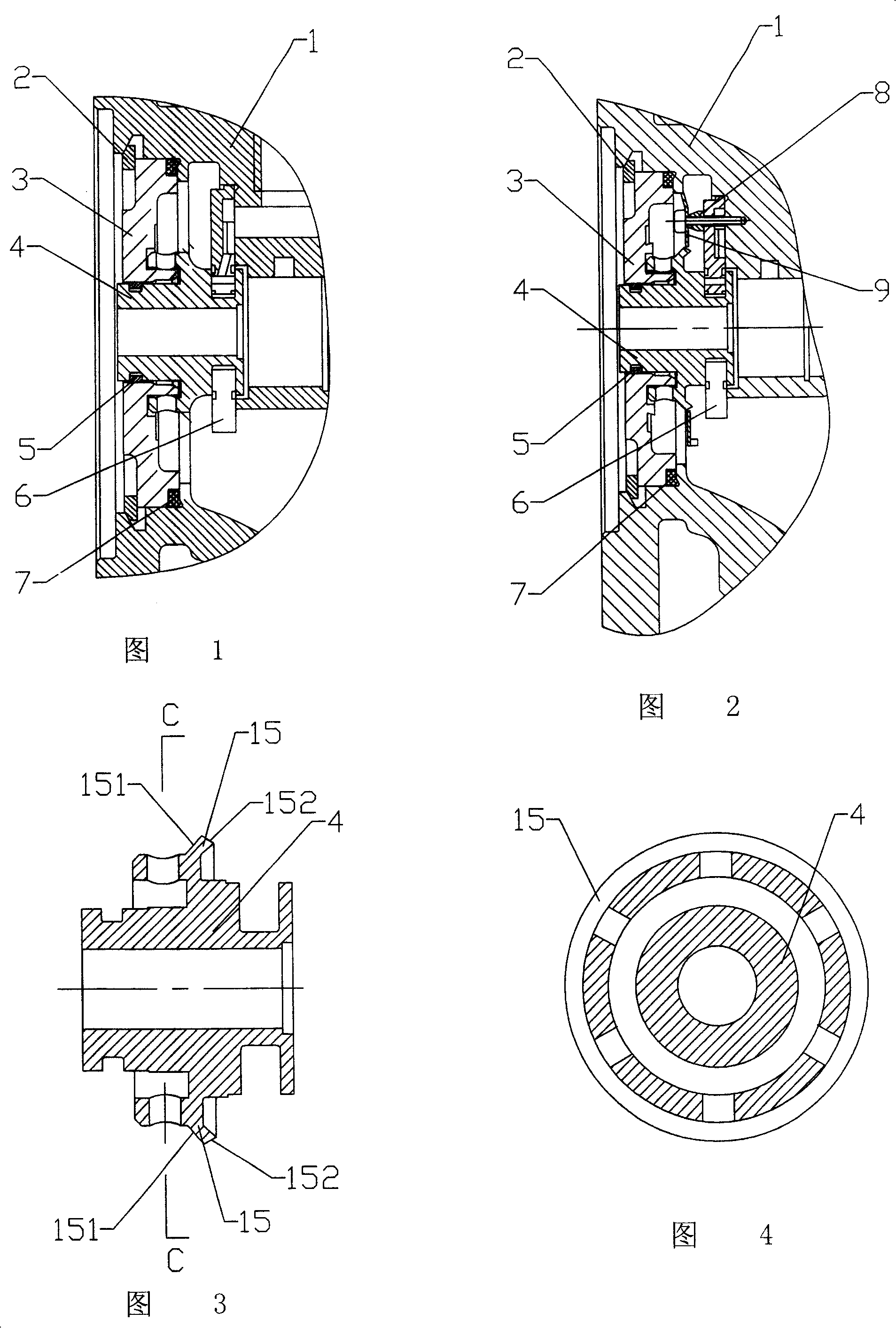
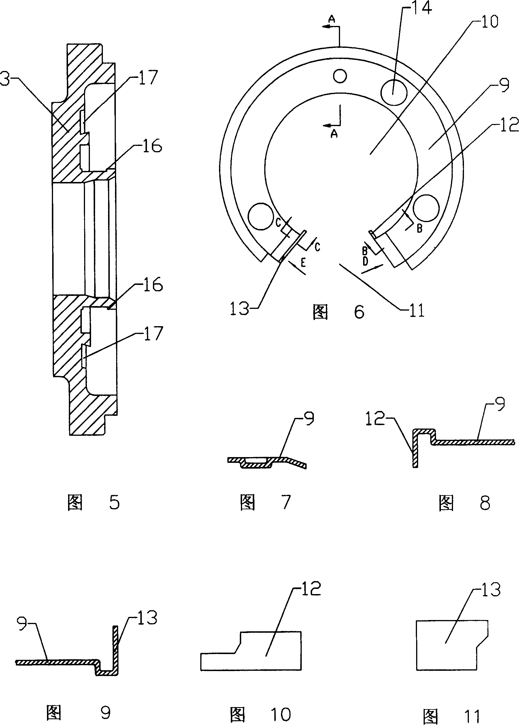
[0037] Embodiment, as shown in Figure 2, a turbocharger compressor end sealing device is composed of an intermediate housing 1, a sealing ring sleeve seat 3, a thrust oil throwing pan 4 and a thrust bearing 6, and the intermediate housing 1 and A circlip 2 for holes and an O-shaped sealing ring 7 are arranged between the sealing ring housing 3, a sealing ring 5 is arranged between the sealing ring housing 3 and the thrust bearing 4, and a sealing ring 5 is arranged between the thrust oil throwing pan 4 and the middle shell. An oil baffle 9 is arranged between the body 1, and the oil baffle 9 is sealed with the thrust oil throwing pan 4 and the intermediate housing 1 respectively, and a support sleeve 8 is provided between the oil baffle 9 and the thrust bearing 6 , the thrust oil throwing pan 4, the thrust bearing 6, and the intermediate housing 1 form an oil-holding cavity, and the oil baffle plate 9 forms a static sealing cavity with the intermediate housing 1 and the thrust ...


PUM


Abstract

The invention relates to a sealing device of turbine pressurizing compressor, which comprises a middle case, a sealing ring base, a retaining oil spray disc, a retaining bearing, and an oil baffle plate between the retaining oil spray disc and the middle case. Wherein, the oil baffle plate, the middle case and the retaining bearing can form a stable sealing chamber; the oil baffle plate is mounted at the inclined surface of annular heave to limit the flowing shape of machine oil with resisting and dividing the machine oil; the case of retaining oil spray disc that connecting the oil container has a annular heave whose inner and outer sides have inclined surface to change the flowing direction; the sealing ring base has a guide groove; the guide groove and the retaining oil spray disc form a guide channel to guide the machine oil leaked from the movable sealing gap between the oil baffle plate and the retaining oil spray disc into the oil reflux cut of middle case. The invention can effectively reduce the oil leakage with wider market prospect.

Description

technical field [0001] The invention relates to a turbocharger compressor end sealing device, which belongs to the field of internal combustion engines. Background technique [0002] my country's turbocharger industry has formed a considerable scale after decades of development. As a new technology, the turbocharger has promoted the development of the internal combustion engine and improved the technical performance of the internal combustion engine. , Such as the forward and backward curved compressor impeller, mixed-flow turbine, the calculation of the three-dimensional flow field and the breakthrough of the turbine dynamometer equipment, etc., have opened up broad prospects for improving the performance of the turbocharger. Although the performance of the turbocharger has been rapidly improved, at present, the sealing problem of the turbocharger is still a weak link of the turbocharger, which is mainly manifested in the oil leakage when the turbocharger is running. How t...

Claims


Application Information

Patent Timeline
Patent Type & Authority Patents(China)
IPC IPC(8): F16J15/26
Inventor 王航郭锡禄郭伦海郑恩君张在生王德亮
Owner KANGYUE TECH
Why Eureka
Try Eureka