
Sewing machine with improved thread cutting mechanism

A sewing machine and thread cutting technology, which is applied in the field of sewing machines, can solve the problems of shortening the thread quantity and unable to maintain the quantity, etc.

Inactive Publication Date: 2008-01-23
BROTHER KOGYO KK
View PDF8 Cites 0 Cited by
  • Summary
  • Abstract
  • Description
  • Claims
  • Application Information

AI Technical Summary

Problems solved by technology

However, in this case, the amount of thread at the thread end on the needle side is reduced so that the amount of thread used for subsequent sewing after thread cutting becomes shorter.
Therefore, in a conventional sewing machine, the cloth and the thread ends on the needle side cannot each hold an appropriate amount after thread trimming

Method used


Image

  • Sewing machine with improved thread cutting mechanism
  • Sewing machine with improved thread cutting mechanism
  • Sewing machine with improved thread cutting mechanism

Examples


Embodiment Construction

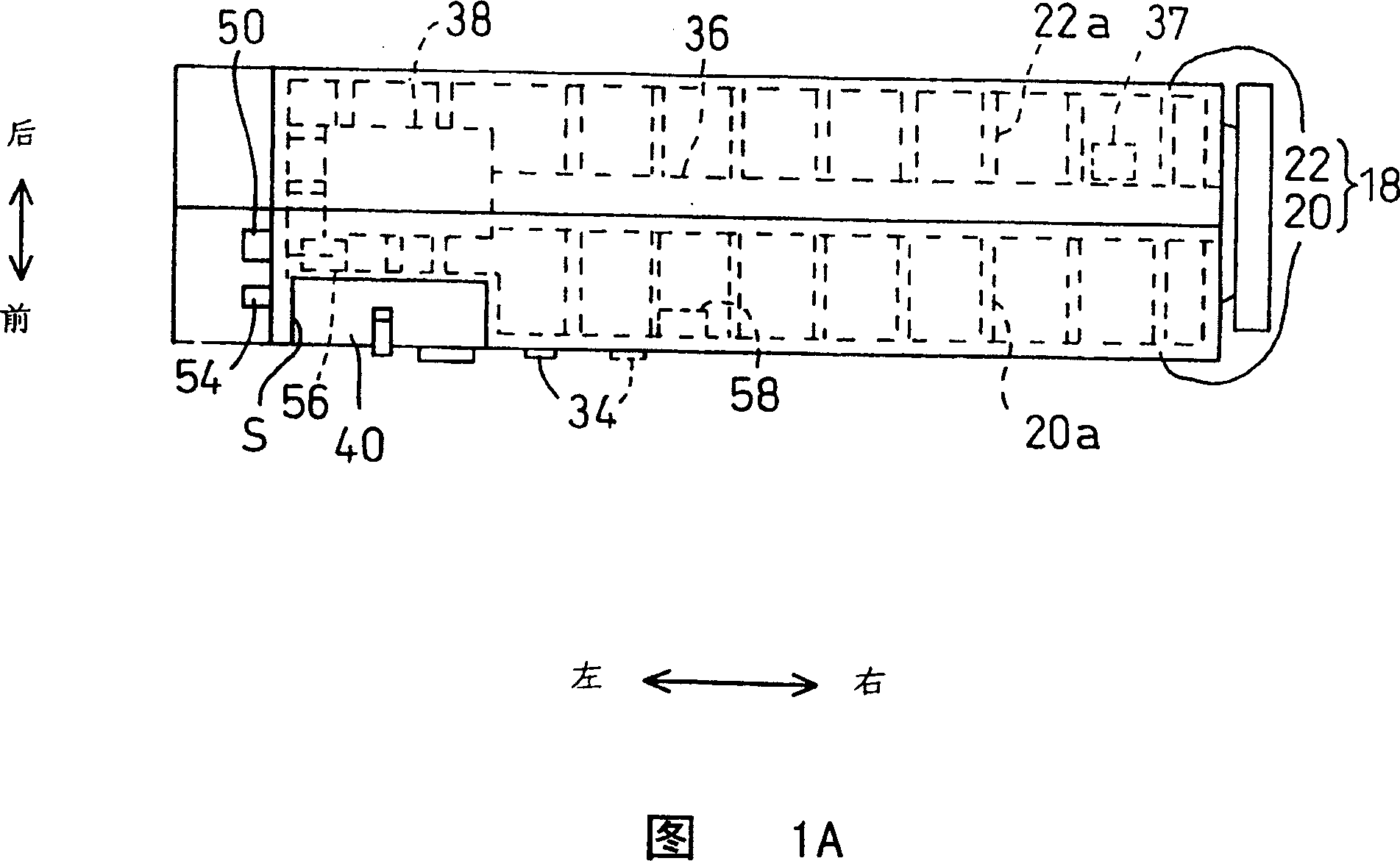
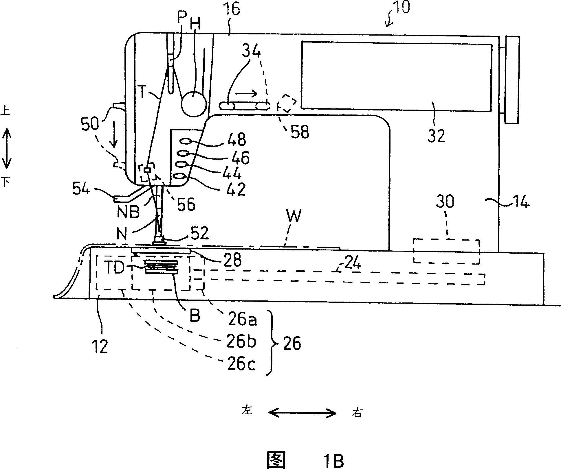
[0050] An embodiment of the present invention will be described in detail with reference to the accompanying drawings. Referring to Fig. 1A and 1B, sewing machine 10 of the present invention comprises: a sewing base plate 12 with horizontal plane; A post 14, this post extends upwards from the right-hand part of base plate 12; The right side extends horizontally so as to be opposite to or above the bottom plate 12 . The bottom plate 12 , the pillars 14 and the arms 16 are continuously formed on a resin cabinet 18 including a front cabinet 20 and a rear cabinet 22 . Japanese Patent Application No. 2001-295564 filed by the assignee of the present application discloses the cabinet as described above.

[0051] A lower shaft 24 made of metal is supported on the rear cabinet 22 so as to extend longitudinally inside the bottom plate 12 as viewed in FIG. 1B . A lower mechanism 26 is mounted on the rear housing 22 at the left-hand end of the shaft 24 . The lower mechanism 26 includes...


PUM


Abstract

A sewing machine includes a needle plate having a needle hole through which a sewing needle is allowed to pass, a thread catcher reciprocally moved forward and backward below the needle plate and being elongated in a moving direction, the thread catcher having a frontward end with respect to a direction of forward movement of the thread catcher and including first and second generally hook-shaped catching portions, and a cutting blade located between the first and second catching portions at least during backward movement of the thread catcher to cut a thread caught between the first and second catching portions. The first catching portion is located nearer to the frontward end of the thread catcher than the second catching portion with respect to the moving direction of the thread catcher during forward movement of the thread catcher. The first catching portion is further spaced from and located nearer to the needle hole of the needle plate than the second catching portion with respect to a direction perpendicular to the moving direction of the thread catcher. The thread catcher is moved backward so that the thread caught between the first and second catching portions intersects the cutting blade.

Description

technical field [0001] The present invention relates to a sewing machine in which a thread to be cut by a cutting blade is hooked under a needle plate. Background technique [0002] A conventional sewing machine includes a thread catcher arranged to reciprocate under a needle plate. The thread catcher is moved so that it passes through a loop, whereby the loop is separated by the thread catcher. The thread catcher catches the thread during its return movement. Move the snagged thread to the cutting blade for cutting. Japanese Patent No. 2871201 issued to the assignee of the present application discloses such a tangential method. In the above-mentioned conventional sewing machine, a movable blade 510 as a thread catcher and a fixed blade 520 include corresponding horizontally extending plate-shaped portions, as shown in FIG. 42 . The wires are separated by a stationary blade 520 . The thread amount of the thread end on the cloth side in the sewing bed depends on the posi...

Claims


Application Information

Patent Timeline
IPC IPC(8): D05B65/02D05B63/00D05B19/12D05B65/00
CPCD05B19/12D05B65/00
Inventor 宇佐修一郎
Owner BROTHER KOGYO KK
Learn More