Transmission X-ray data collection system and computer X-ray tomography system

A data acquisition system and data acquisition technology, applied in computing, image data processing, image data processing, etc.

Inactive Publication Date: 2008-01-23
GE MEDICAL SYST GLOBAL TECH CO LLC +1
View PDF3 Cites 0 Cited by
  • Summary
  • Abstract
  • Description
  • Claims
  • Application Information

AI Technical Summary

Problems solved by technology

At this time, the product value of tube current and energization time determined relative to the middle position of the scan is not always suitable for other positions

Method used


Image

  • Transmission X-ray data collection system and computer X-ray tomography system
  • Transmission X-ray data collection system and computer X-ray tomography system
  • Transmission X-ray data collection system and computer X-ray tomography system

Examples


Embodiment Construction

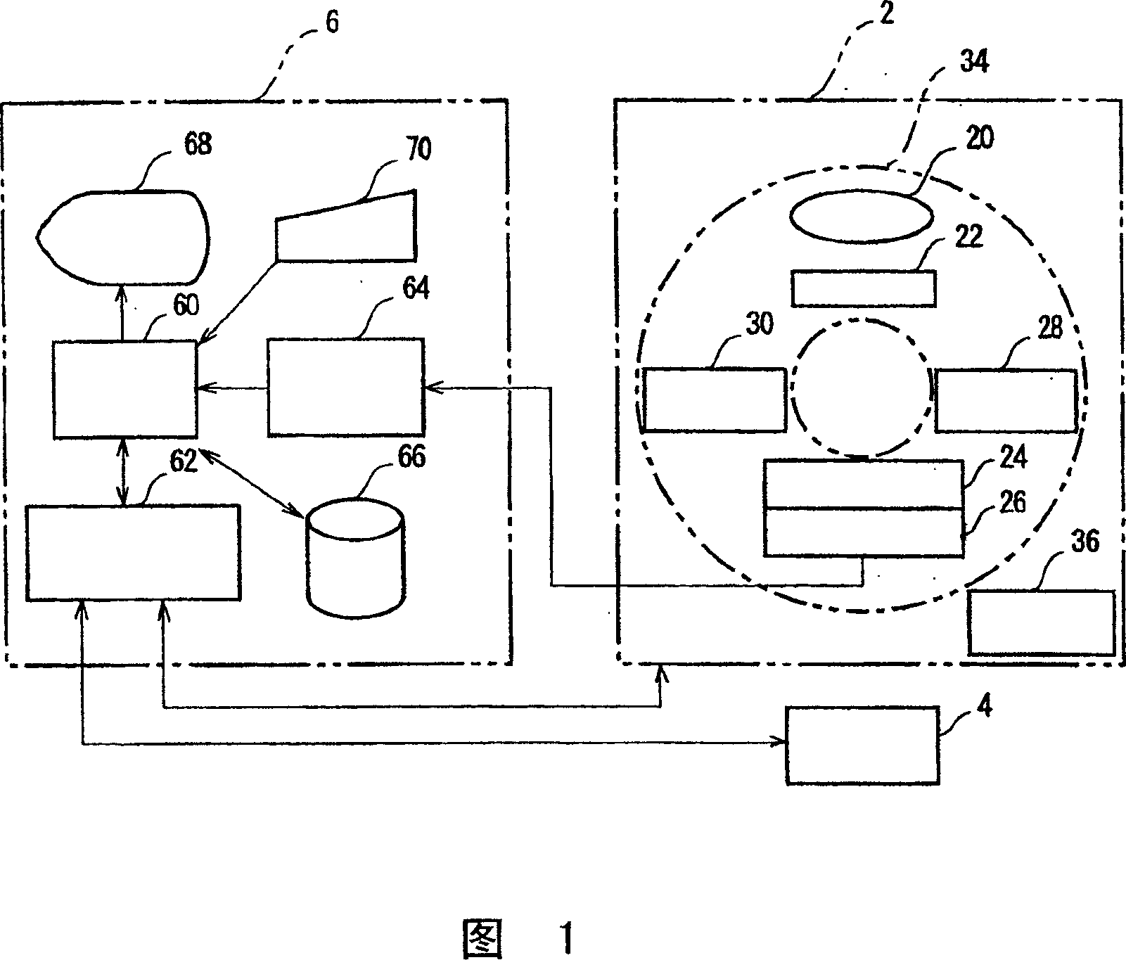
[0053] An embodiment of the present invention will be described below with reference to the accompanying drawings. Figure 1 is a block diagram of a computed tomography (X-ray CT) system. This system is an example of an embodiment of the invention. The configuration of this system is an example of an embodiment of a computed tomography system implementing the present invention. Each operation of this system is an example of an embodiment realizing the computed tomography method of the present invention.

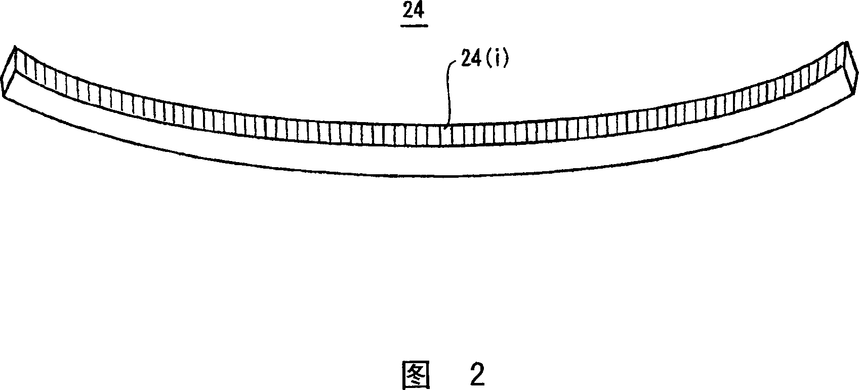
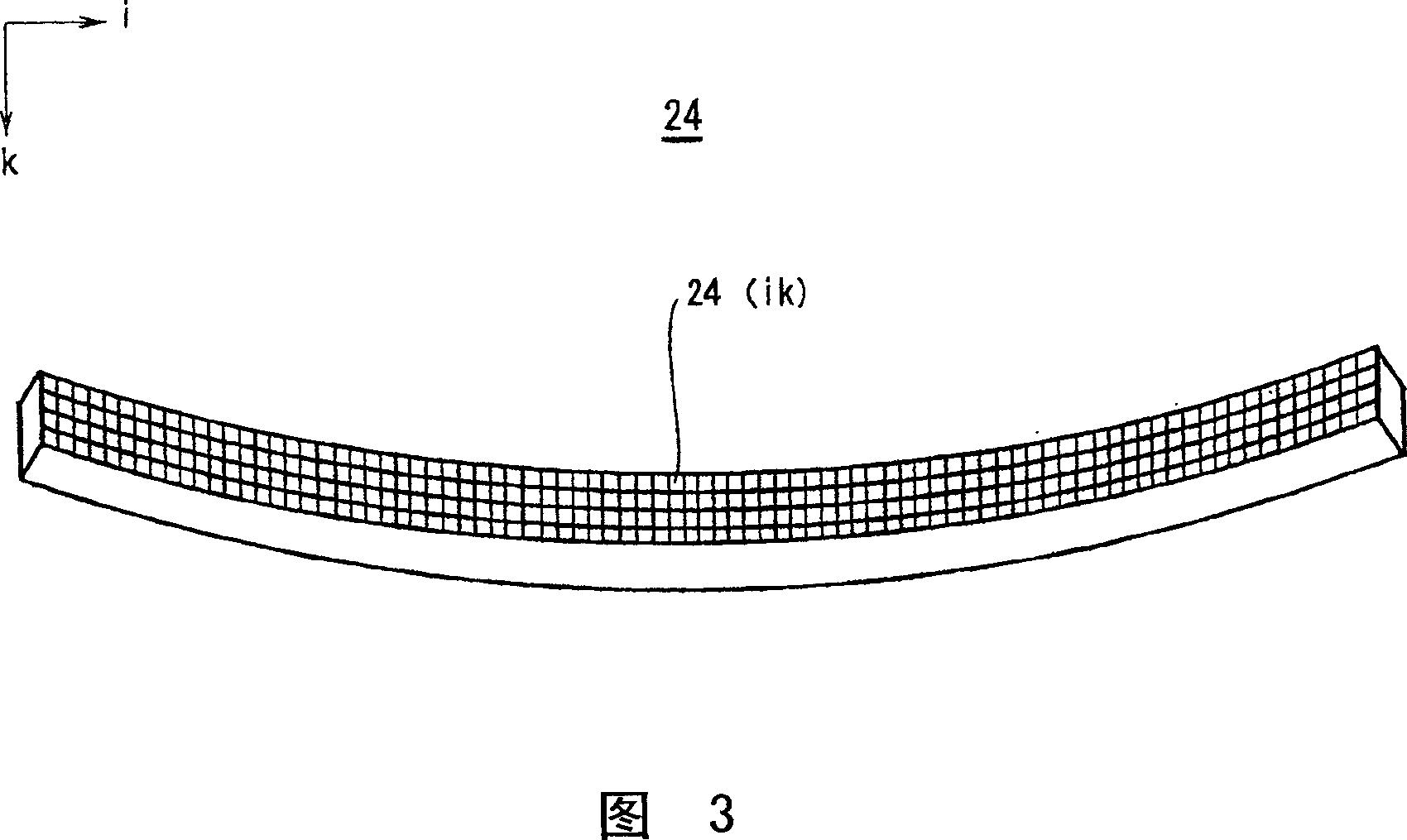
[0054] As shown in FIG. 1 , the system mainly includes a scanner gantry 2 , a radiographing platform 4 , and an operator console 6 . The scanner gantry 2 includes an X-ray tube 20 . The X-rays (not shown) emitted from the X-ray tube 20 are recomposed by the collimator 22 into fan-shaped X-ray beams, ie fan beams, and irradiated onto the X-ray detector 24 . Here, X-ray tube 20 and collimator 22 constitute an example of an embodiment of an X-ray emitter encompassed by the pr...


PUM


Abstract

Transmitted X-ray data is acquired by irradiating X-rays of appropriate doses determined for the portions of a section containing the major axis and the portions thereof containing the minor axis respectively. An X-ray irradiating / detecting device consists mainly of an X-ray irradiator that includes an X-ray tube (20) and irradiates a fan-shaped X-ray beam (400), and an X-ray detector (24) that has a plurality of X-ray detecting elements arrayed in a direction in which the fan-shaped X-ray beam spreads and that is opposed to the X-ray irradiator with an object of imaging (8) between them. The X-ray irradiating / detecting device is rotated (2,4) about the object in order to acquire transmission X-ray data stemming from a plurality of views. At this time, the dose of the X-ray beam is differentiated between predetermined angular ranges of a section of the object shaped like an oval, which extend with the minor axis of the oval section as a centerline, and the other angular ranges.Transmitted X-ray data is acquired by irradiating X-rays of appropriate doses determined for the portions of a section containing the major axis and the portions thereof containing the minor axis respectively. An X-ray irradiating / detecting device consists mainly of an X-ray irradiator that includes an X-ray tube (20) and irradiates a fan-shaped X-ray beam (400), and an X-ray detector (24) that has a plurality of X-ray detecting elements arrayed in a direction in which the fan-shaped X-ray beam spreads and that is opposed to the X-ray irradiator with an object of imaging (8) between them. The X-ray irradiating / detecting device is rotated (2,4) about the object in order to acquire transmission X-ray data stemming from a plurality of views. At this time, the dose of the X-ray beam is differentiated between predetermined angular ranges of a section of the object shaped like an oval, which extend with the minor axis of the oval section as a centerline, and the other angular ranges.

Description

technical field [0001] The invention relates to a transmission X-ray data acquisition system and a computerized X-ray tomography system. More specifically, the present invention relates to a transmission X-ray data acquisition system for generating X-ray tomographic images based on transmitted X-ray data and a computerized X-ray system for generating tomographic images based on the collected transmission X-ray data X-ray tomography system. Background technique [0002] In a computed tomography system, an X-ray emission / detection device acquires transmitted X-ray data representing the transmitted X-rays of an imaging object and generates (reconstructs) a tomographic image of the object based on the transmitted X-rays . The X-ray emitter emits an X-ray beam with a width large enough to cover the tomographic layer or X-ray section of the object, and the X-ray beam also has a certain thickness. The X-ray detector is a multi-channel X-ray detector which has a plurality of arr...

Claims


Application Information

Patent Timeline
Patent Type & Authority Patents(China)
IPC IPC(8): A61B6/03G01N23/00A61B6/00A61B6/02G01N23/04G06T1/00
CPCG01N23/046A61B6/027G01N2223/419
Inventor 堀内哲也
Owner GE MEDICAL SYST GLOBAL TECH CO LLC
Why Eureka
Try Eureka