
Technology and apparatus for forming worm channel with plastic liner of centrifugal pump

一种成型方法、离心泵的技术,应用在泵、泵元件、非变容式泵等方向,能够解决生产效率低、离心泵效率和水力特性下降、防腐耐磨性能下降等问题,达到提高衬塑效率和成品率、提高效率及水力特性、节约生产成本的效果

Inactive Publication Date: 2008-01-16
YIXING ZHOUSI PUMP IND CO LTD
View PDF6 Cites 0 Cited by
  • Summary
  • Abstract
  • Description
  • Claims
  • Application Information

AI Technical Summary

Problems solved by technology

However, the flow path with a circular track will cause the efficiency and hydraulic characteristics of the centrifugal pump to decrease, and this decrease is more obvious especially in small flow and high pressure centrifugal pumps.
In order to overcome the defect that the molded lining cannot obtain the ideal volute track flow channel, Chinese patent 86100758 discloses a method and mold for molding the lining by using a parting block mold. The flow channel is designed and a number of combinable and disassembled volute blocks and mandrel combined molds are used as the lining mold, which are formed by heating and unidirectional extrusion, so that a lining plastic layer with a volute flow channel is obtained between the inner and outer molds
This lining method, first, the production efficiency is low; second, due to the complex flow path of the volute of the pump body, the density of the unidirectional extrusion lining layer is low, which is easy to cause shrinkage, which reduces the anti-corrosion and wear resistance, and it is difficult to obtain Uniform and dense overall lining layer, especially in larger pumps, this defect is more obvious
In order to overcome the above deficiencies, Chinese patent 96117172 has made improvements to it, disclosing a lining method and mold using bidirectional extrusion molding, but only partially overcomes the defects of low density and unevenness of the lining layer, and the production efficiency has not been improved. improve
In addition, the above-mentioned direct lining method and mold with a volute flow channel not only have low production efficiency and high cost; moreover, the assembly and disassembly process is cumbersome, and the mold clamping pressure required is high, and the mold, especially the outer mold of the pump casing, is easily damaged.
Then there is the direct molding of the lining spiral channel, which can only be lined with ultra-high molecular weight polyethylene with low molecular weight and high melt index, but this will reduce the wear resistance of the lining layer. To obtain a molded lining that is both corrosion-resistant and wear-resistant High molecular weight polyethylene is more difficult

Method used


Image

  • Technology and apparatus for forming worm channel with plastic liner of centrifugal pump
  • Technology and apparatus for forming worm channel with plastic liner of centrifugal pump
  • Technology and apparatus for forming worm channel with plastic liner of centrifugal pump

Examples


Embodiment

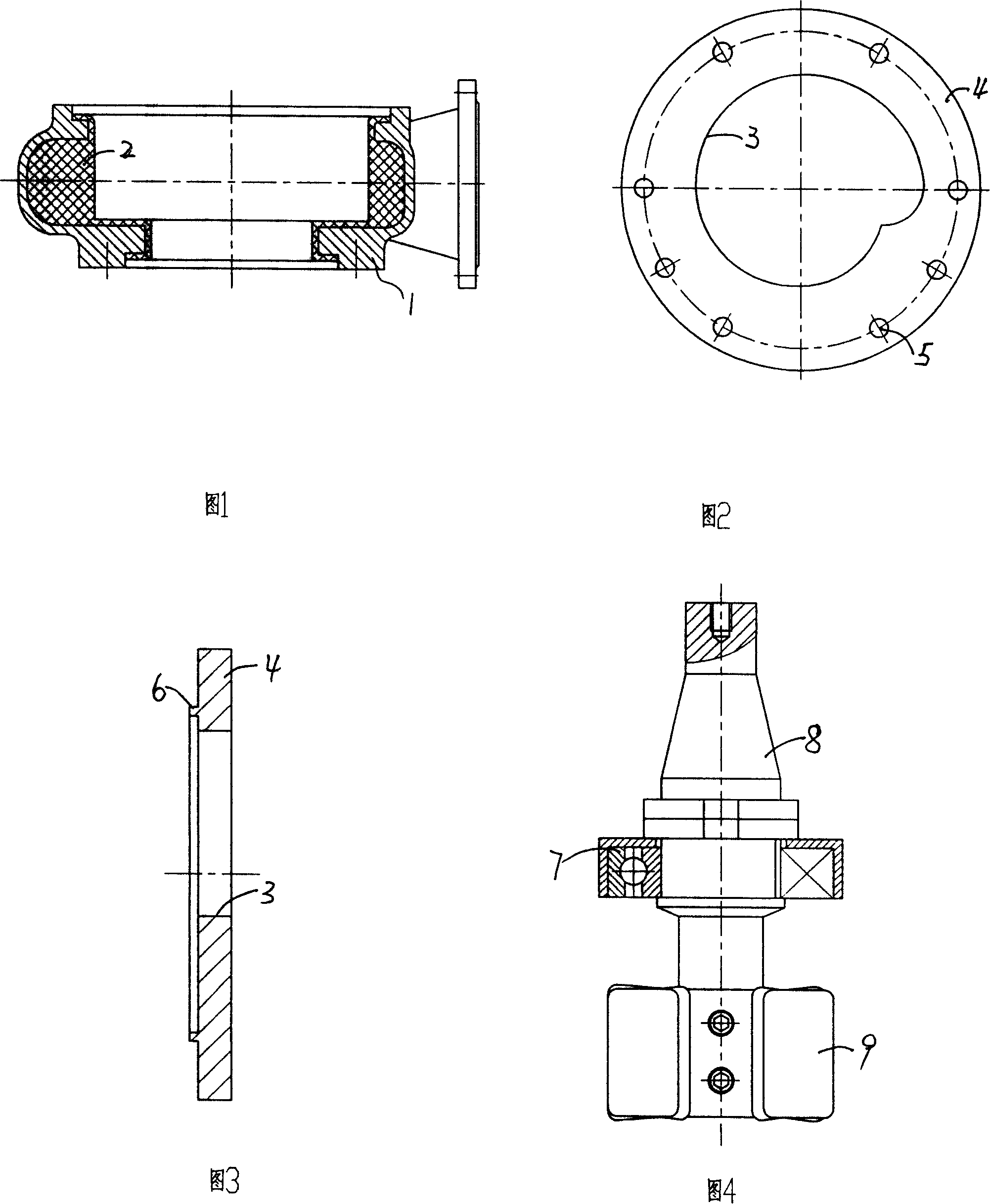
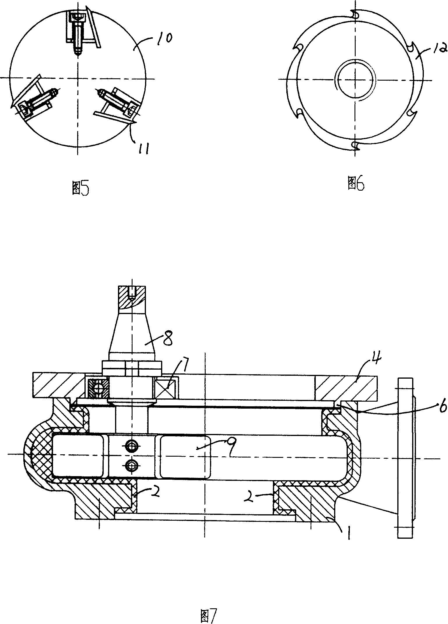
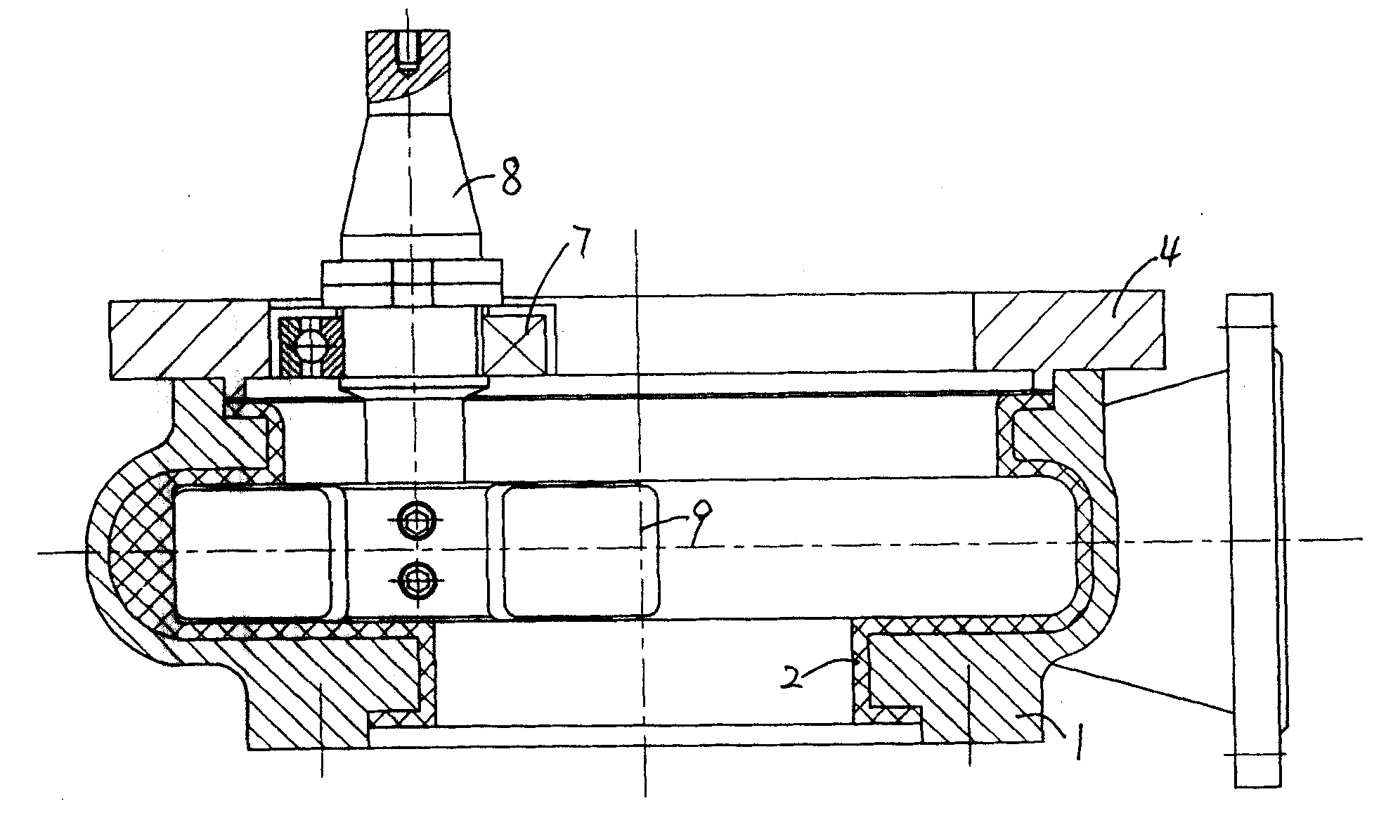
[0014] Embodiment: Referring to the accompanying drawings, the metal volute 1 of an involute centrifugal pump is used as the outer mold, and a circular or approximately circular flow path with a certain thickness is obtained as a lining by a molding method. Ultra-high molecular weight polyethylene or polypropylene lining plastic layer 2 (Figure 1). Then, the milling template 4 ( FIG. 2 ) with the volute flow channel 3 matched with the front pump cover is fixed on the front pump cover side of the metal pump body 1 ( FIG. 7 ) through the fixing screw hole 5 . In order to facilitate accurate positioning, the inside of the milling template is provided with a positioning convex ring 6 (Fig. 3). Bearing 7 (Fig. 4) is provided in the positioning sleeve at the location of the milling mold runner track corresponding to the tool handle 8 of the milling cutter 9 having the same width as the runner. During the cutting process, the bearing on the milling tool shank is attached to the inne...


PUM


Abstract

A technology for machining the worm-shaped channel with plastic liner for centrifugal pump includes such steps as die pressing a plastic liner with a certain thickness onto the the metallic worm of centrifugal pump, and milling according to designed template of said channel. Its advantages include high efficiency and flexibility, and low cost.

Description

technical field [0001] The invention relates to the improvement of the plastic-lined centrifugal pump, in particular to the molding of the plastic-lined flow channel of the centrifugal pump. Background technique [0002] In order to solve the transportation of corrosive and granular media, an economical and effective way is to use steel-lined plastic centrifugal pumps, that is, to compound a layer of corrosion-resistant and wear-resistant plastic layer with a certain thickness on the lining of the metal pump body of the centrifugal pump. , such as ultra-high molecular weight polyethylene. However, due to the low fluidity of plastics with corrosion-resistant and wear-resistant properties, usually only the molded lining method can be used, and at present, for lining such plastics, in order to facilitate demoulding and obtain a lining layer with higher density and certain thickness, use The metal pump body of the centrifugal pump is used as the outer mold, and the inner plasti...

Claims


Application Information

Patent Timeline
Patent Type & Authority Patents(China)
IPC IPC(8): B29C63/26F04D7/06F04D29/42
Inventor 蒋龙福蒋兆平陈小生
Owner YIXING ZHOUSI PUMP IND CO LTD
Learn More