Record carrier, playback device and method of recording information

a playback device and information recording technology, applied in the field of record carriers, can solve the problems of degrading the detection of recorded information, and the detection of the modulation pattern itsel

Inactive Publication Date: 2013-12-24
KONINKLJIJKE PHILIPS NV
View PDF33 Cites 0 Cited by
  • Summary
  • Abstract
  • Description
  • Claims
  • Application Information

AI Technical Summary

Benefits of technology

[0009]For this purpose, the record carrier as described in the opening paragraph, is characterized in that, with respect to a code track having the modulation pattern, a modulation pattern in a left neighboring track is aligned to a modulation pattern in a right neighboring track. The code track is a track which carries, in its modulation pattern, the code for controlling the data processing when retrieving the recorded information. One or more (or all) tracks on the record carrier may be code tracks. The aligned modulation patterns in the tracks neighboring the code track have the effect that second variations in the left neighboring track are complementary to second variations in the right neighboring track, because irregularities in the second variations due to the modulation are present in both neighboring tracks. Hence, any increase in disturbance caused by a second variation in the left neighboring track is compensated by a decrease in disturbance by a complementary variation in the right neighboring track. Therefore, the tight tolerances on the parameters of the track can effectively be maintained and crosstalk remains limited to acceptable values.
[0010]The invention is also based on the following recognition. The amplitude of the second variations must be sufficiently strong for detecting the modulation pattern. However, in a high-density record carrier, the modulation of the second variations in neighboring tracks causes crosstalk, and, therefore, causes noise which degrades the detection of the recorded information and detection of the modulation pattern itself. Hence, the amplitude of the second variations must be as low as possible. The inventors have recognized that by using aligned modulation in neighboring tracks, the maximum noise contribution of the left track does not coincide with the maximum noise contribution of the right track. Hence, a relatively low amplitude of the second variations is sufficient for reliable detection of the modulation pattern. Because of the low amplitude, disruption of the reading of the marks and errors in the retrieved information are minimized.
[0011]An embodiment of the record carrier according to the invention is characterized in that the second variations are displacements of the track in a direction transverse to the longitudinal direction of the track, and displacements of the left neighboring track coincide with displacements of the right neighboring track in the same direction. This has the advantage that the crosstalk of the first variations in adjacent tracks is reduced, because if said excursion in the one adjacent track is towards the position of a read spot on the code track and, hence, causes some additional crosstalk, the excursion of the other adjacent track is away from the read spot and, hence, causes less crosstalk.
[0012]An embodiment of the record carrier according to the invention is characterized in that the modulation patterns in the code track and the neighboring tracks represent the same code. This has the advantage, that the detection signal of the code track will be stronger because the neighboring tracks have the same modulation. Further, if the second parameter is an excursion in a transverse direction, the distance between the tracks, also called track pitch, at the modulated parts of the track still remains the same, because both tracks have the same transverse excursion. Alternatively, the modulation pattern in the code track is substantially inverse to the modulation pattern in the left neighboring track. This has the advantage for some modulation types, e.g., a wobble in a pre-groove, that the detection signal of the code track is stronger.
[0013]An embodiment of the record carrier according to the invention is characterized in that the second variations are periodic and the modulation pattern comprises phase modulation, and phase differences between modulation patterns in adjacent tracks are limited to a predetermined amount. Such a predetermined amount is selected to be smaller than phase differences occurring in said phase modulation. This has the advantage that any disturbance of the neighboring tracks is substantially in phase with a read signal from the modulation pattern in the code track.
[0015]The playback device as described in the opening paragraph, is characterized in that the device comprises means for retrieving the code from at least two tracks. In the record carrier, the aligned modulation patterns result in at least two tracks having the same modulation pattern and, therefore, representing the same code. In the playback device, the code retrieved from a first track is verified by reading a further track, which carries the same code. This has the advantage that the retrieval of the code is more reliable.

Problems solved by technology

Therefore, the tight tolerances on the parameters of the track can effectively be maintained and crosstalk remains limited to acceptable values.
However, in a high-density record carrier, the modulation of the second variations in neighboring tracks causes crosstalk, and, therefore, causes noise which degrades the detection of the recorded information and detection of the modulation pattern itself.

Method used


Image

  • Record carrier, playback device and method of recording information
  • Record carrier, playback device and method of recording information
  • Record carrier, playback device and method of recording information

Examples


Embodiment Construction

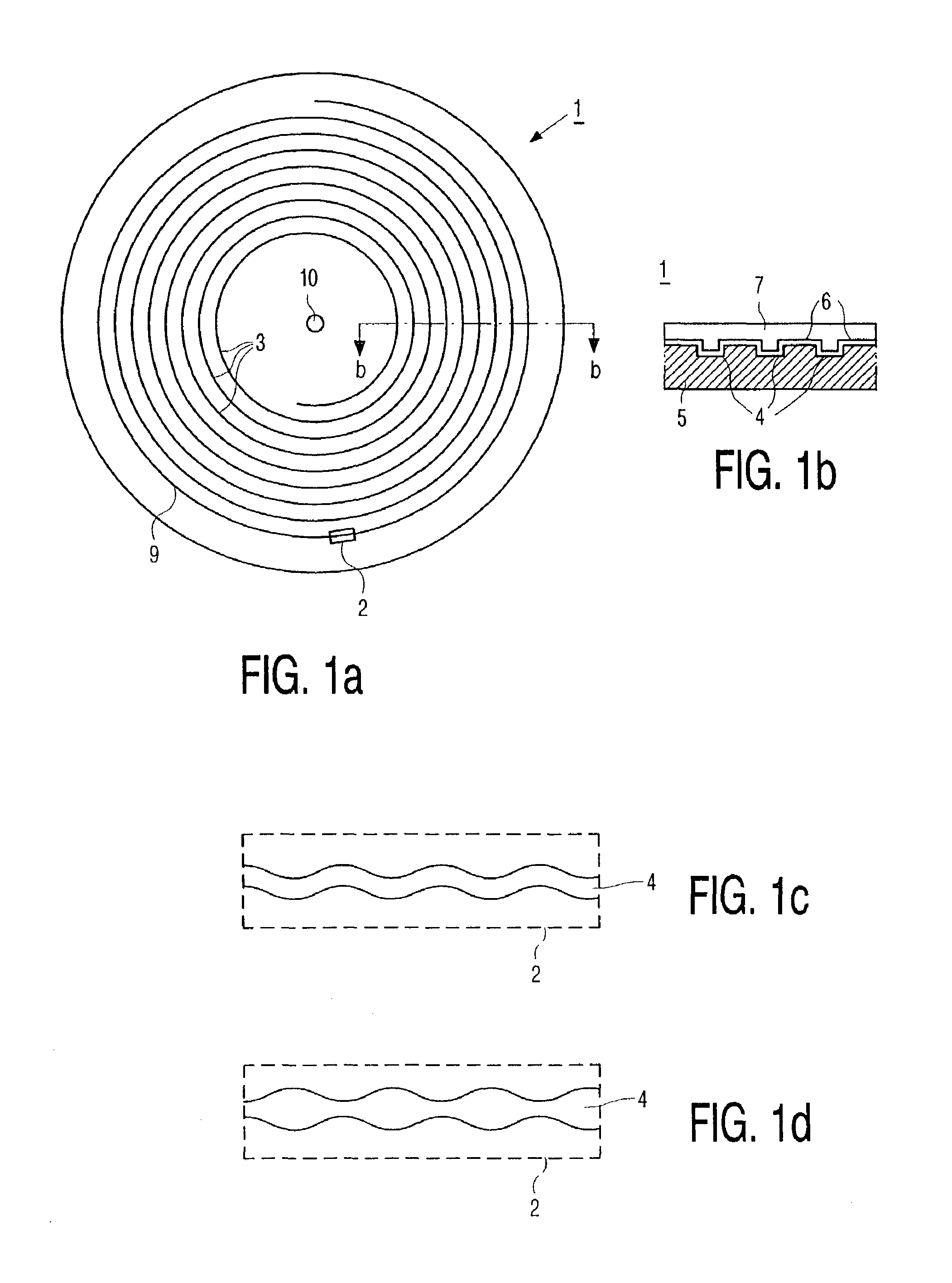
[0024]FIG. 1a shows a disc-shaped record carrier 1 having a track 9 and a central hole 10. The track 9 is arranged in accordance with a spiral pattern of turns constituting substantially parallel tracks on an information layer. The record carrier may be an optical disc having an information layer of a recordable type or of a prerecorded type. Examples of a recordable disc are the CD-R and CD-RW, and the DVD+RW, whereas the audio CD or the DVD video are examples of prerecorded discs. The prerecorded type can be manufactured in a well-known way by first recording a master disc and, via intermediate steps, subsequently pressing consumer discs. The track 9 on the recordable type of record carrier is indicated by a pre-embossed track structure provided during manufacture of the blank record carrier, for example, a pre-groove. The information is represented on the information layer by optically detectable marks recorded along the track. The marks are constituted by variations of a first p...


PUM

PropertyMeasurementUnit
radiiaaaaaaaaaa
frequencyaaaaaaaaaa
frequencyaaaaaaaaaa

Abstract

A record carrier has substantially parallel tracks having first variations of a first physical parameter and second variations of a second physical parameter of the track. The first variations represent information recorded on the record carrier, this information being recoverable by a controllable type of data processing. A modulation pattern of the second variations represents a code for controlling the type of data processing. In respect of a code track that includes the modulation pattern, the modulation pattern in the left neighboring track is aligned to the modulation pattern in the right neighboring track. Thereby crosstalk due to the second variations is decreased, and at least two tracks have the same modulation pattern. The playback device has a demodulator (50) and a control unit (56) for retrieving the code from at least two tracks.

Description

CROSS-REFERENCE TO RELATED APPLICATIONS[0001]This is a reissue application of patent U.S. Pat. No. 7,054,245 which issued on May 30, 2006 from an application Ser. No. 10 / 382,674, filed Mar. 6, 2003, which is a continuation of U.S. patent application Ser. No. 09 / 488,027, filed Jan. 20, 2000, now U.S. Pat. No. 6,549,495 which issued on Apr. 15, 2003, and which claims foreign priority from EP 99200217.0, filed Jan. 27, 1999.BACKGROUND OF THE INVENTION[0002]1. Field of the Invention[0003]The invention relates to a record carrier comprising substantially parallel tracks having first variations of a first physical parameter of the track, the first variations representing information recorded on the record carrier, the information being recoverable by a controllable type of data processing; and second variations of a second physical parameter of the track, a modulation pattern of the second variations representing a code for controlling said type of data processing.[0004]The invention furt...

Claims


Application Information

Patent Timeline
Patent Type & Authority Patents(United States)
IPC IPC(8): G11B7/00G11B7/004G11B7/007G11B7/09G11B7/24082G11B20/00G11B20/10G11B20/14G11B20/18G11B27/19G11B27/24G11B27/30
CPCG11B7/007G11B7/00736G11B7/24082G11B20/00086G11B20/00405G11B20/1833G11B27/24G11B20/00586G11B7/004G11B2220/2562G11B20/1419G11B27/3027G11B2220/218G11B2220/2545G11B7/24079G11B20/1217G11B2007/00709G11B2007/00754G11B2020/1238G11B2020/1267G11B2020/1278
Inventor SPRUIT, JOHANNES H. M.VAN DEN ENDEN, GIJSBERT JOSEPHLINNARTZ, JOHAN P. M. G.TALATRA, JOHAN C.
Owner KONINKLJIJKE PHILIPS NV
Why Eureka
Try Eureka