
Control of data transmission between a remote monitoring unit and a central unit

a technology of remote monitoring and central unit, which is applied in the field of control of data transmission between a remote monitoring unit and a central unit, can solve the problems of large transmission-time cost and the depletion of the batteries and achieve the effects of reducing the amount of data, reducing the time and cost of cellular telephone connection, and increasing the lifetime of the remote monitoring uni

Inactive Publication Date: 2012-10-23
BRAEMAR MFG
View PDF160 Cites 59 Cited by
  • Summary
  • Abstract
  • Description
  • Claims
  • Application Information

AI Technical Summary

Benefits of technology

[0006]The present invention provides an approach for monitoring a patient and providing support to the patient. The present approach adopts a new data transfer architecture with improved selectivity of data transmission but retention of the data accumulation capability to build the patient history and also the emergency capability to assist the patient on an urgent basis when needed. The battery power of the remote monitoring unit is thereby used more judiciously, the cellular telephone connect time is reduced, and medical personnel time is better managed.
[0011]This selective transmission approach, wherein data transmission from the remote monitoring unit is not automatic but instead is under control of the central unit, reduces the amount of data that must be transmitted over a cellular telephone connection or similar expensive communication device. This selectivity reduces cellular telephone connect time and charges to the user, and also may significantly increase the lifetime of the remote monitoring unit between battery charging, because establishing and maintaining the cell phone connection constitutes a significant portion of the battery usage of the remote monitoring unit. The human resources of the medical personnel at or in communication with the central unit are also better utilized. Only those situations that are more likely to be actual emergencies are brought to the attention of those medical personnel, so that they have more time for such potential actual emergencies.

Problems solved by technology

That approach is likely to produce unnecessarily large and unnecessarily frequent data transfers which result in depletion of the batteries of the remote monitoring unit and large transmission-time costs.

Method used


Image

  • Control of data transmission between a remote monitoring unit and a central unit
  • Control of data transmission between a remote monitoring unit and a central unit
  • Control of data transmission between a remote monitoring unit and a central unit

Examples


Embodiment Construction

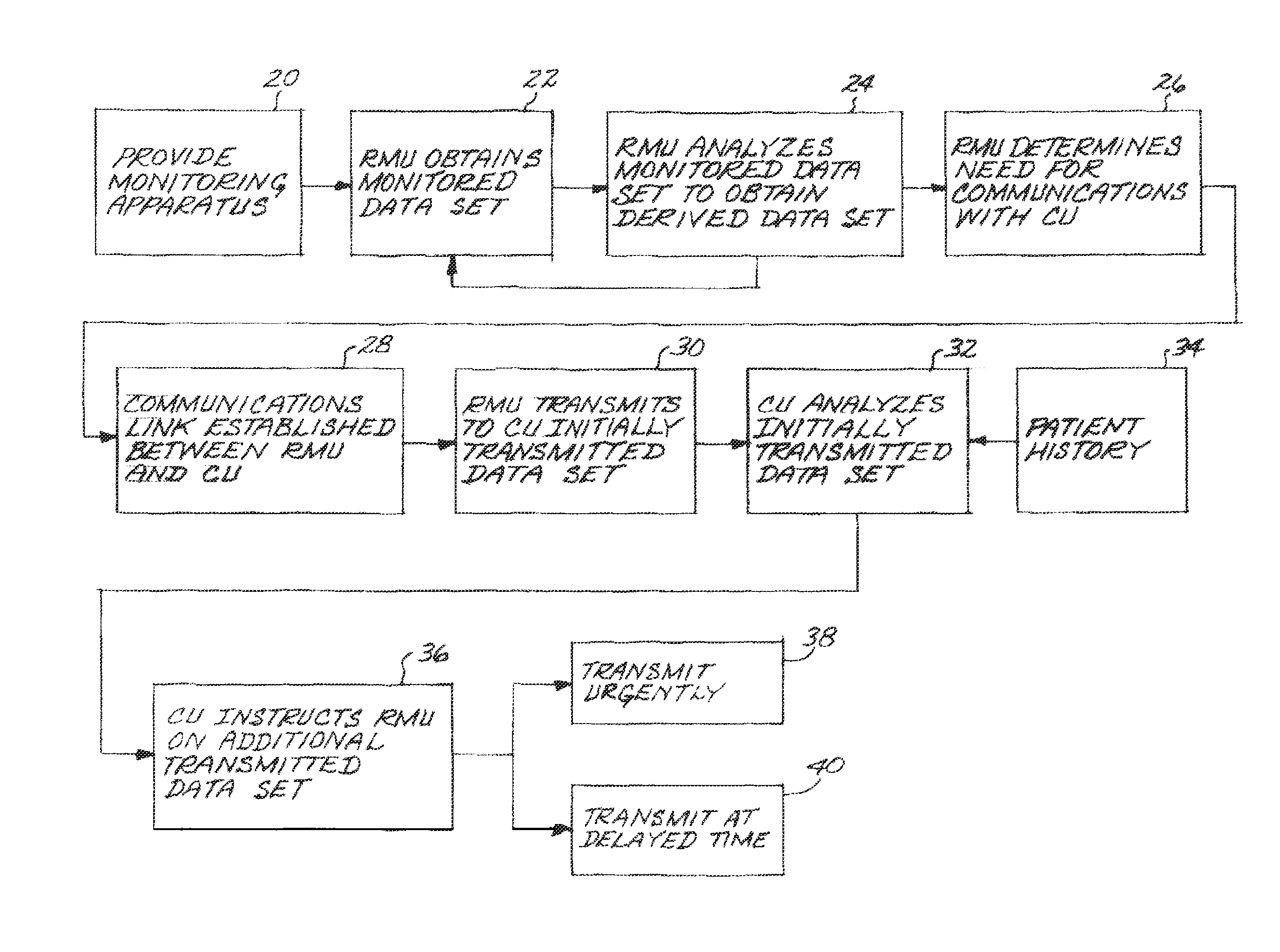
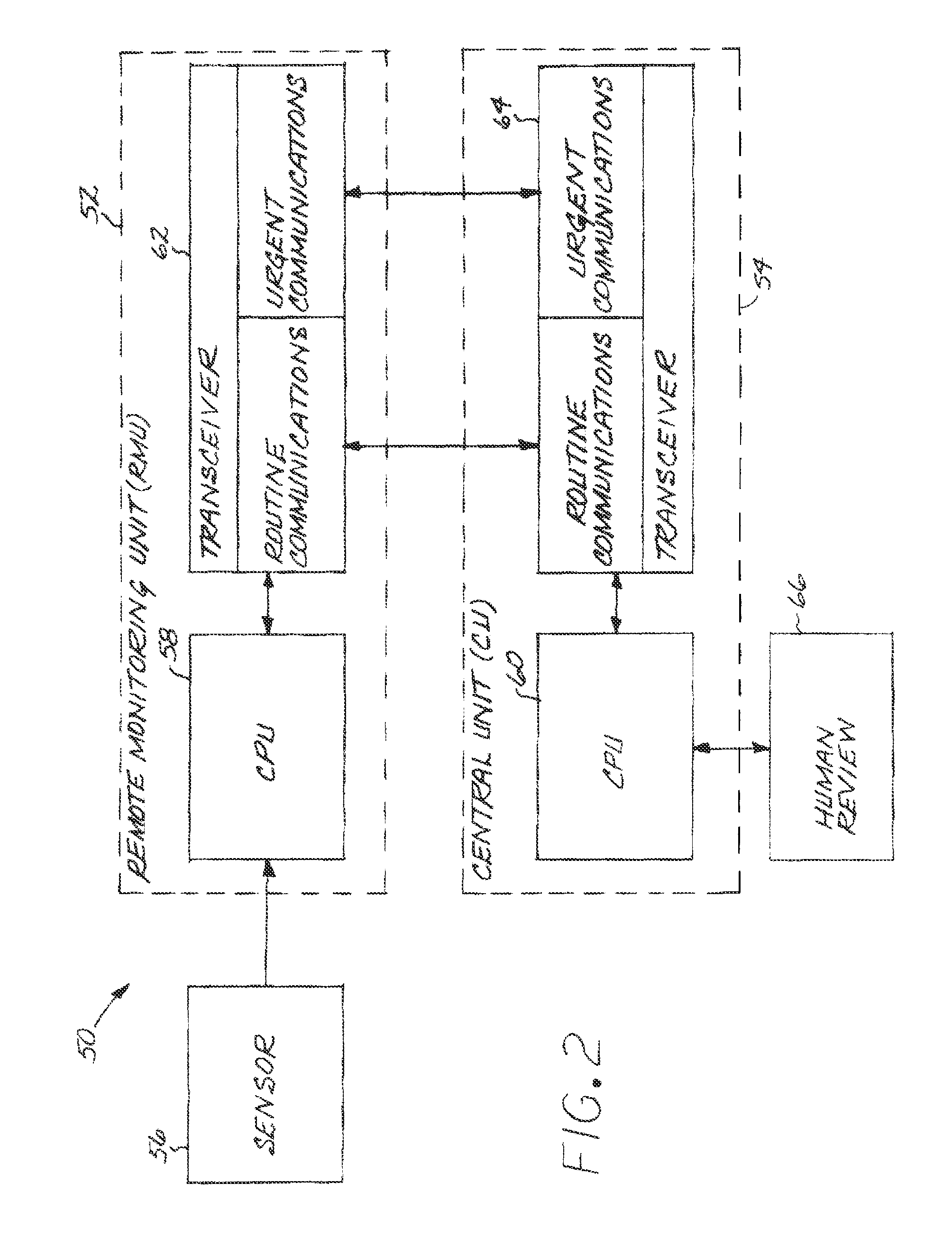
[0015]FIG. 1 depicts an approach for practicing the present invention. A monitoring apparatus is provided, numeral 20. The monitoring apparatus may be of any operable form, and one preferred form of the monitoring apparatus 50 is illustrated in FIG. 2. The monitoring apparatus 50 is shown in a simplified form illustrating only those portions that are required to discuss the present invention. More detail of a monitoring apparatus may be found in U.S. Pat. No. 5,959,529, whose disclosure is incorporated by reference.

[0016]The monitoring apparatus 50 includes a remote monitoring unit (RMU) 52 carried by an ambulatory patient, and a central unit (CU) 54. The central unit 54 may be a single computer, but it is more typically a file server or a network. Other remote monitoring units, that are not “portable” in the sense that they are not carried on the person of the patient but may be at a fixed location in a patient's home or hospital facility, may be used as well. A sensor 56 measures ...


PUM


Abstract

A patient is monitored using a monitoring apparatus including a remote monitoring unit associated with the patient and having a sensor that measures a physiological characteristic of the patient, a central unit, and a communications device which selectively establishes a communications link between the remote monitoring unit and the central unit. The remote monitoring unit obtains a monitored data set for the patient, analyzes the monitored data set to obtain a derived data set from the monitored data set, and determines from the derived data set that communication with the central unit is required. A communications link is established with the central unit, and the remote monitoring unit transmits to the central unit an initially transmitted data set related to the monitored data set. The central unit analyzes the initially transmitted data set and instructs the remote monitoring unit as to any additional transmitted data set related to the monitored data set that is to be transmitted from the remote monitoring unit to the central unit and a time at which the additional transmitted data set is to be transmitted.

Description

[0001]This invention relates to the transmission of data between a remote monitoring unit and a central unit, and more particularly to the optimization of such data transfer.BACKGROUND OF THE INVENTION[0002]Advances in sensor technology, electronics, and communications have made it possible for physiological characteristics of patients to be monitored even when the patients are ambulatory and not in continuous, direct contact with a hospital monitoring system. For example, U.S. Pat. No. 5,959,529 describes a monitoring system in which the patient carries a remote monitoring unit with associated physiological sensors. The remote monitoring unit conducts a continuous monitoring of one or more physiological characteristics of the patient according to the medical problem of the patient, an example being the heartbeat and its waveform.[0003]Under prescribed conditions, the remote monitoring unit contacts a central unit to communicate information on the condition of the patient. For examp...

Claims


Application Information

Patent Timeline
IPC IPC(8): A61B5/04A61B5/00
CPCA61B5/0002A61B2560/0209A61B2560/0271
Inventor EGGERS, PHILIP N.SEVERE, LON M.
Owner BRAEMAR MFG
Learn More