
Method and system for image processing

Inactive Publication Date: 2012-10-16
INTELLECTUAL VENTURES I LLC
View PDF63 Cites 2 Cited by
  • Summary
  • Abstract
  • Description
  • Claims
  • Application Information

AI Technical Summary

Benefits of technology

[0024]The invention provides an image processing system for the creating and editing images that are resolution independent and characterized by a series of layers, or image objects, that can be combined together to yield an output image, at any resolution, for display or print. The new method of image processing in a computerized system creates a high performance image representation, that yields much faster image processing by supplying data defining an original image into the system and reorganizing the original image data.
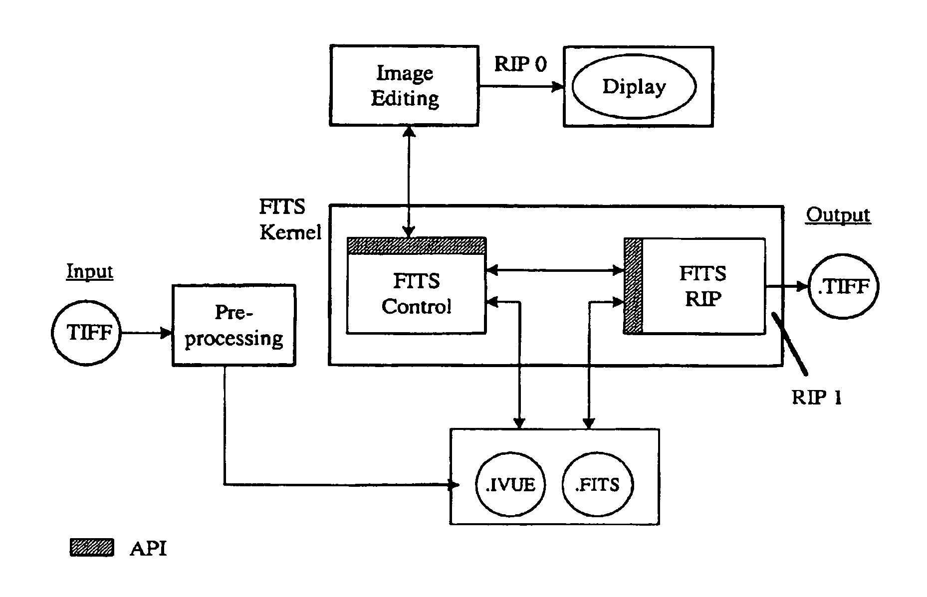
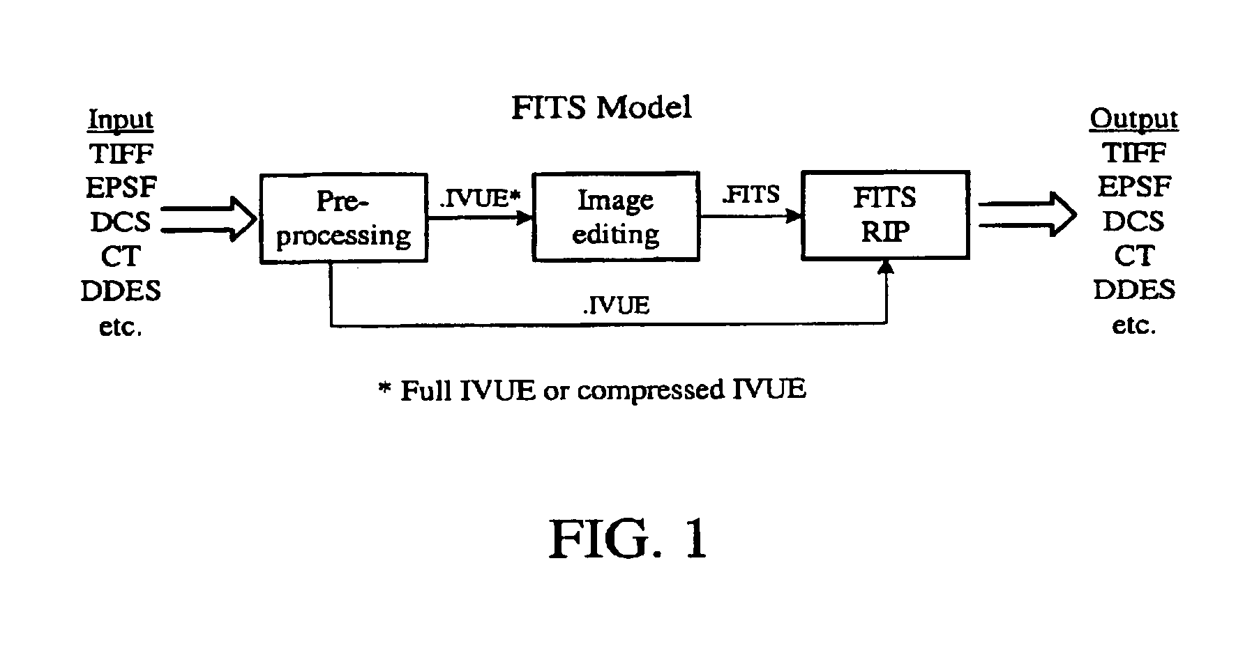
[0025]One aspect of this method (pre-processing, which I call “IVUE” format) comprises the following steps: (1) supplying data defining the original image into the system, (2) assigning pixels from the original image to pixels in the new image format in such a way that the new image is organized in groups (preferably rectangles and most preferably squares), each of which can be individually compressed (using JPEG or another compression algorithm) to yield reduced image size and faster access over a network, (3) creating a second, lower resolution, image by averaging groups of pixels falling within a first predetermined area (or neighborhood) into an averaged pixel, and performing this computation across the entire original image; this second image is also organized in groups, e.g. squares, (4) repeating the previous step, and thereby creating succession of decreasing resolution images, which are stored adjacent to the first two, until a number of pixels less than or equal to a preselected number of pixels remain, and (5) saving the resulting image representation on a storage device.
[0028]Also provided is a method for image processing in a computerized system that enables a raster image to be computed, either with the ability of displaying the image on a computer monitor or for printing the image.
[0030]The invention may use a method of image processing in a computerized system, comprising: (a) supplying data defining an original image into the system, (b) assigning pixels from the original image to pixels in a new first image format so that the first image is organized into groups of pixels, each of the groups being individually compressible to yield a reduced size image, and (c) reducing the number of assigned pixels to form a reduced resolution image by averaging (preferably using a Gaussian function to weight the average for pixel proximity) a particular number of adjacent pixels falling within a first (preferably predetermined) area into a first averaged pixel, organized by the groups of pixels, and performing this computation across the entire first image format, to form a reduced definition image.

Problems solved by technology

Each of these two approaches overcomes some major obstacles, however neither fully responds to the needs of today's color professionals for high quality, and fast response at an affordable price.
When retouching is complete, the script is typically passed to a more powerful, and expensive, server and “executed.” That is, the actions contained in the script are applied to the high res image, which results in a high quality final image.
The disadvantage of this approach is that the operator does not work with the actual image or at highly detailed levels (particularly for a magnified “close-up” of a portion).
As a result, it is not always possible to perform highly detailed retouching actions such as silhouetting and masking.
Moreover, unpleasant surprises may occur upon execution.
The virtual image approach suffers two important shortcomings: first, large amounts of memory are required; and second, each effect is applied immediately to the entire image so that complex manipulation, such as large airbrushing, scaling and rotation, incur long processing delays.
Due to the high amount of memory required for processing, personal computers have proven very slow and marginally acceptable.
Moreover, even with larger mainframe systems, there is not always a good correlation between the monitor and the printed image since there is not always a way to visualize the final image on the display device.
Thus, discrepancies can be introduced due to differences between screen resolution and print resolution.
Perhaps the greatest disadvantage of known procedures stems from the image that is displayed on the monitor not being identical to the image that will eventually be printed, rendering the operator unable to see the work as it will actually appear in print.
Anomalies and discrepancies can therefore occur in the printed image.
Known procedures cannot resolve the fact that the image displayed on the operator's monitor screen is in most cases vastly less defined than the scanned image held in the computer's memory.
(This is untrue only in the case of small, low resolution images.)
A second and perhaps equally important disadvantage of known image processing techniques is that the image editing effects are applied sequentially, i.e. step-by-step.
This incurs a severe degradation in the quality of the original image if many image editing effects are applied to the same portion of an image.
If processing power is unavailable, then the time required to carry out the operation becomes unacceptably long, thus reducing the scope and sophistication of possible operations to be carried out on the image.
For example, airbrush strokes are currently extremely limited in size as a result of the extreme processing power needed to calculated image changes.
The irreversible nature of image processing using known procedures precludes the operator from easily implementing any second thoughts.
However, this requires a huge amount of memory (e.g., a single 8½″×11″×300 dots per inch (dpi) figure requires over 33 million bytes).
To sum up, current computerized image processing for obtaining a high definition image suffers from the dual disadvantages of requiring extremely high processing power, a limitation of productivity and creativity for the operator due to the irreversibility of image editing steps, and the quality restrictions inherent in a pixel-based approach.

Method used


Image

  • Method and system for image processing
  • Method and system for image processing
  • Method and system for image processing

Examples


examples

1) Airbrushing

[0156]This involves in making a line with a color. As this line imitates that made by an airbrush, it can be treated as a succession of colored dots created by the airbrush spray. The distribution of the color density in a airbrush dot is a Gaussian function. This means that the intensity of the color is at its greatest in the center of the dot, diminishing towards the edges as a Gauss function. In a real airbrush, the intensity depends on the pressure exerted on the trigger, which widens or otherwise changes the ink spray within the air jet. Such a pressure can be simulated in a computerized system by representing (as explained above) a dot by a circle of color with a density variation between the center and edge expressed as a Gauss function. The saturation at the center can vary between 0 and 1 (or zero and 100%).

[0157]To sum up, the line of an aerograph is a succession of colored disks, of which it is possible to modify the path (the location of the disk centers), ...


PUM


Abstract

A method for image processing in a computerized system reduces the amount of memory required for image processing and produces a layered effect which permits complex manipulation such as scaling and rotation without long delay, while allowing earlier versions of the visual image to be recalled. The method involves pre-processing, image editing and raster image processing.

Description

[0001]This invention relates to computer processing in general, and more particularly to a method and system for image processing. This patent application is a divisional of U.S. application Ser. No. 09 / 712,019, filed Nov. 13, 2000, now U.S. Pat. No. 6,512,855 which is a divisional of U.S. application Ser. No. 08 / 933,798, filed Sep. 19, 1997, now U.S. Pat. No. 6,181,836, which is a continuation of U.S. application Ser. No. 08 / 327,421, filed on Oct. 21, 1994, now U.S. Pat. No. 5,790,708, which is a continuation of U.S. application Ser. No. 08 / 085,534, filed on Jun. 30, 1993, now abandoned. This patent application also claims priority of French patent application No. 93.03455, filed Mar. 25, 1993, the contents of which are herein incorporated by reference.BACKGROUND OF THE INVENTION[0002]The present invention was created in response to the shortcomings of the current generation of image retouching systems. Other retouching systems use one of two methods for handling images: (1) high r...

Claims


Application Information

Patent Timeline
IPC IPC(8): G06K9/36G06K9/32H04N5/262G06F3/048G06F3/14G06T3/00G06T3/40G06T11/60G09G5/00
CPCG06T3/00G06T3/4007G06T3/4092G06T11/60G06T3/02G06T1/00
Inventor DELEAN, BRUNO
Owner INTELLECTUAL VENTURES I LLC
Learn More