
Video signal processing circuit and computer system

a video signal and processing circuit technology, applied in the field of video signal processing circuits, can solve the problems of wasteful power consumption, limited driving time, and shorter operating time of the whole system, and achieve the effect of eliminating unnecessary a/d conversion and preventing wasteful power consumption in the circui

Inactive Publication Date: 2008-05-20
XYLON LLC +1
View PDF22 Cites 1 Cited by
  • Summary
  • Abstract
  • Description
  • Claims
  • Application Information

AI Technical Summary

Benefits of technology

[0010]It is a first object of the present invention, putting attention to a received video signal itself, to provide a video signal processing circuit which can prevent wasteful power consumption in the circuit as a whole by eliminating unnecessary A / D conversion according to a video signal.
[0011]It is a second object of the present invention to provide a computer system which can prevent wasteful power consumption in the system as a whole by applying therein the video signal processing circuit which achieves the first object.
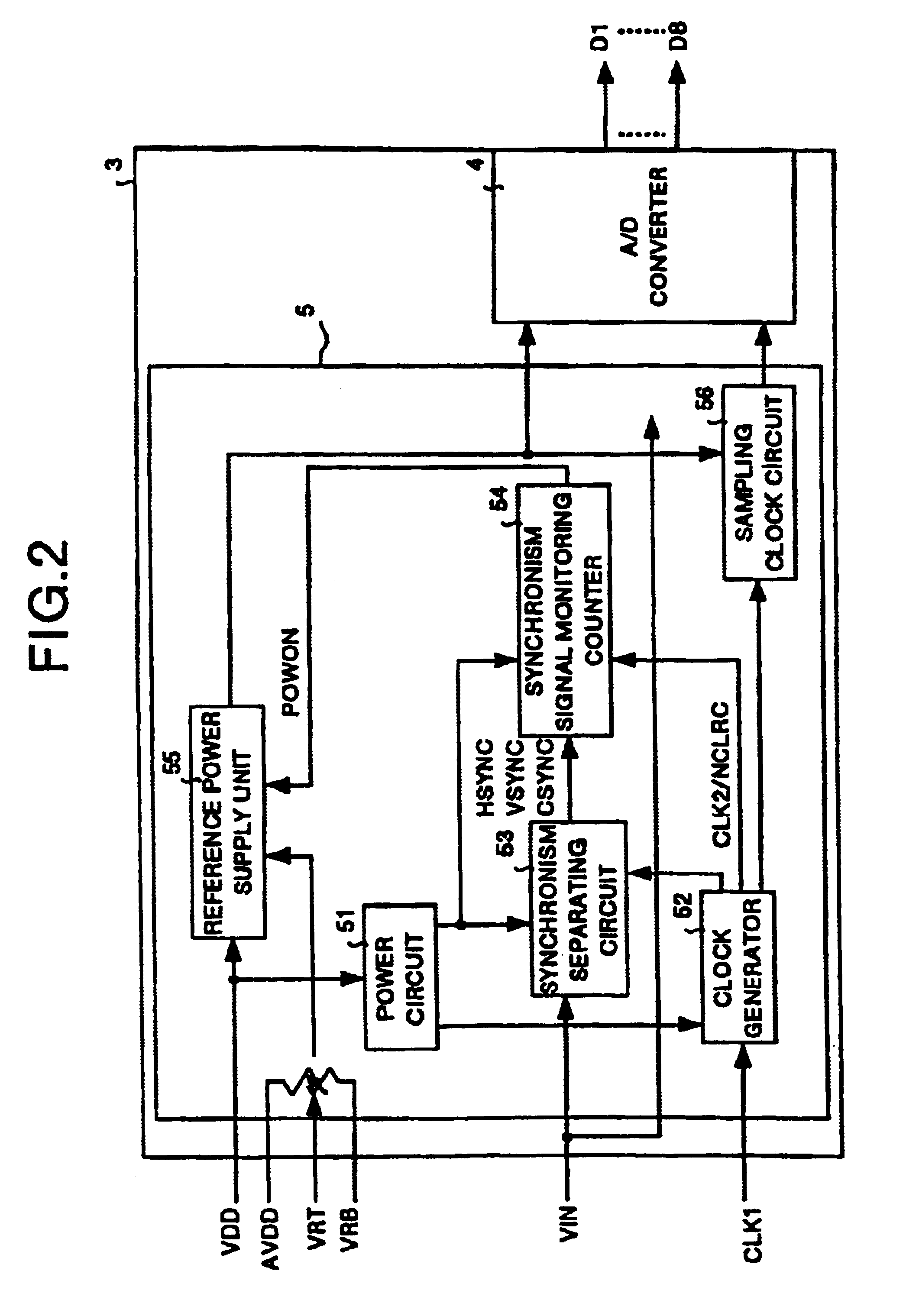
[0012]With the present invention, power supply for A / D conversion is controlled according to a synchronizing signal to an input analog video signal, so that unnecessary A / D conversion is eliminated according to a video signal, and with this feature, it is possible to prevent wasteful power consumption in a circuit as a whole.

Problems solved by technology

In this battery-driven system, a driving time is limited because of correlation between a battery life and a driving time.
For this reason, even when it is conceivable from the view point of an A / D converter and a video signal processing circuit as a peripheral unit thereof or of the system as a whole that, even when the sampling driving is not needed, power is supplied to an A / D converter and the power is wastefully consumed, which makes an operating time of the whole system shorter.

Method used


Image

  • Video signal processing circuit and computer system
  • Video signal processing circuit and computer system
  • Video signal processing circuit and computer system

Examples


Embodiment Construction

[0025]Detailed description is made hereinafter for a preferred embodiment of a video signal processing circuit and a computer system according to the present invention with reference to the accompanying drawings. It should be noted that description assumes an NTSC system as a television system in the embodiment described below.

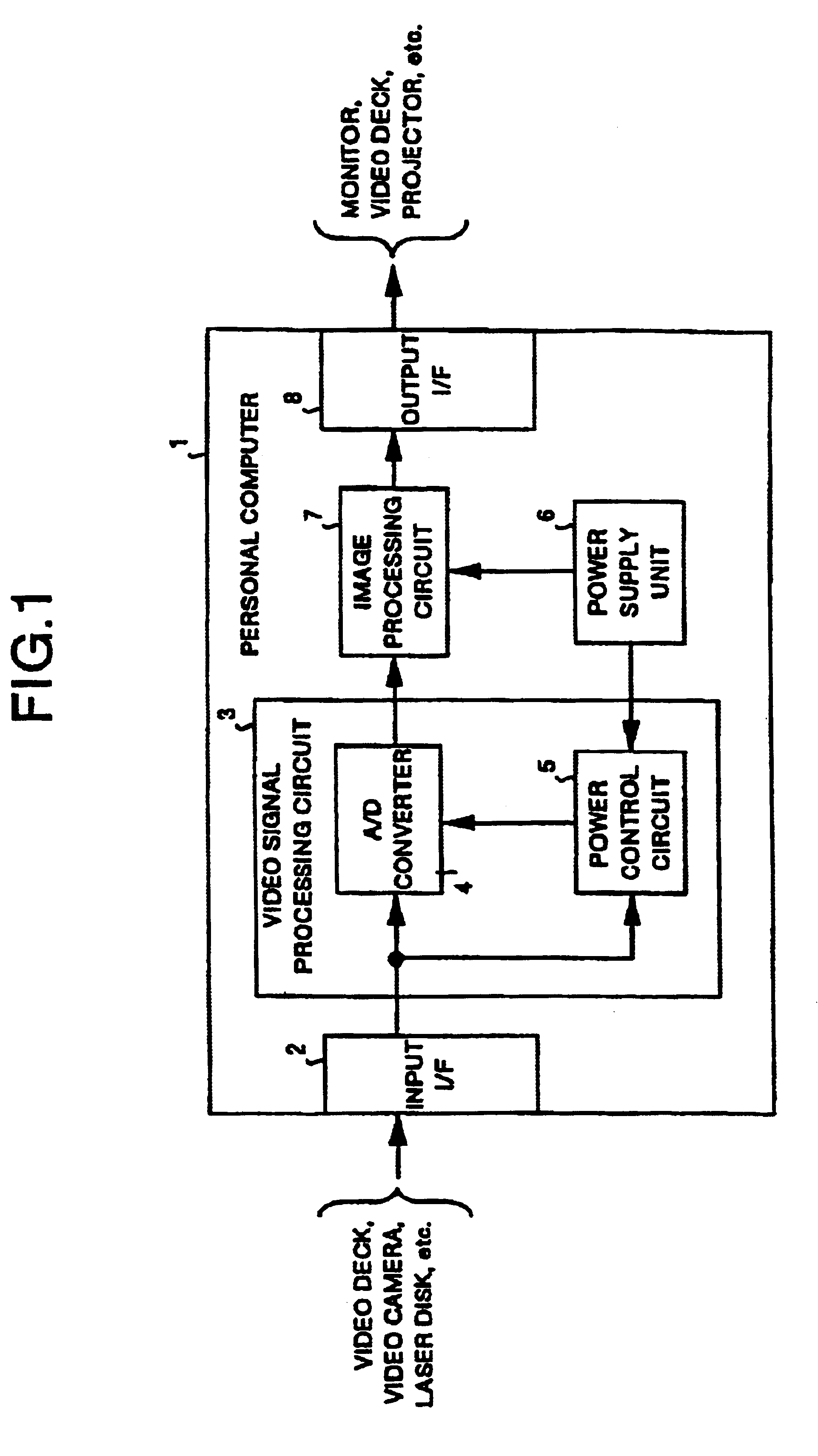
[0026]At first, description is made for system configuration. FIG. 1 is a block diagram showing a computer system according to one embodiment of the present invention. FIG. 1 shows a personal computer 1 as one example of a computer system. This computer system 1 comprises an input I / F 2 for interfacing with input units such as a video deck, a video camera and a laser disk drive to receive input of a video signal; a video signal processing circuit 3; a power supply unit 6 comprising a battery for supplying power into the device; an image processing circuit 7; and an output I / F 8 for interfacing with output devices such as a monitor, a video deck, and a projecto...


PUM


Abstract

A video signal processing circuit, in which a horizontal synchronizing signal is separated from an input analog video signal by a synchronism separating circuit, whether a “H” period of the horizontal synchronizing signal continues for more than a prespecified period of time or not is checked by a synchronizing signal monitoring counter, and power supply to an A / D converter is controlled thereby according to a result the confirmation.

Description

CROSS REFERENCE TO RELATED APPLICATIONS[0001]More than one reissue application has been filed for the reissue of U.S. Pat. No. 6,621,523. The reissue applications are application Ser. Nos. 11 / 229,447 (the present application) and 11 / 827,147(which is a continuation of 11 / 229,447).[0002]This application is a Continuation of U.S. application Ser. No. 09 / 040,424, filed Mar. 18, 1998, now allowed.[0003]This application is based upon and claims priority of U.S. application Ser. No. 09 / 040,424, filed Mar. 18, 1998, and Japanese patent application no. 9-284041, filed Oct. 16, 1997, the contents being incorporated herein by reference.FIELD OF THE INVENTION[0004]The present invention relates to a video signal processing circuit for controlling power supply required for A / D conversion of an analog video signal as well as to a computer system with the video single processing circuit applied therein.BACKGROUND OF THE INVENTION[0005]In recent years, a battery-driven system has generally been empl...

Claims


Application Information

Patent Timeline
Patent Type & Authority Patents(United States)
IPC IPC(8): H04N5/63H04N5/14G09G3/20G09G5/00G09G5/36H04N5/10H04N9/04
CPCG06F1/3203G06F1/3265G09G5/00G09G5/006G09G5/12G09G5/36G09G2330/02G09G2330/021G09G2330/022H04N5/08H04N5/10H04N5/63Y02D10/00
Inventor OBITSU, TOSHIRO
Owner XYLON LLC
Learn More