
Chronograph timepiece

a technology of chronograph and timepiece, which is applied in the direction of generating/distributing signals, instruments, horology, etc., can solve the problems of unnecessary driving, deviation in drive timing, etc., and achieve the effect of preventing wasteful power consumption

Inactive Publication Date: 2012-07-17
SEIKO INSTR INC
View PDF7 Cites 1 Cited by
  • Summary
  • Abstract
  • Description
  • Claims
  • Application Information

AI Technical Summary

Benefits of technology

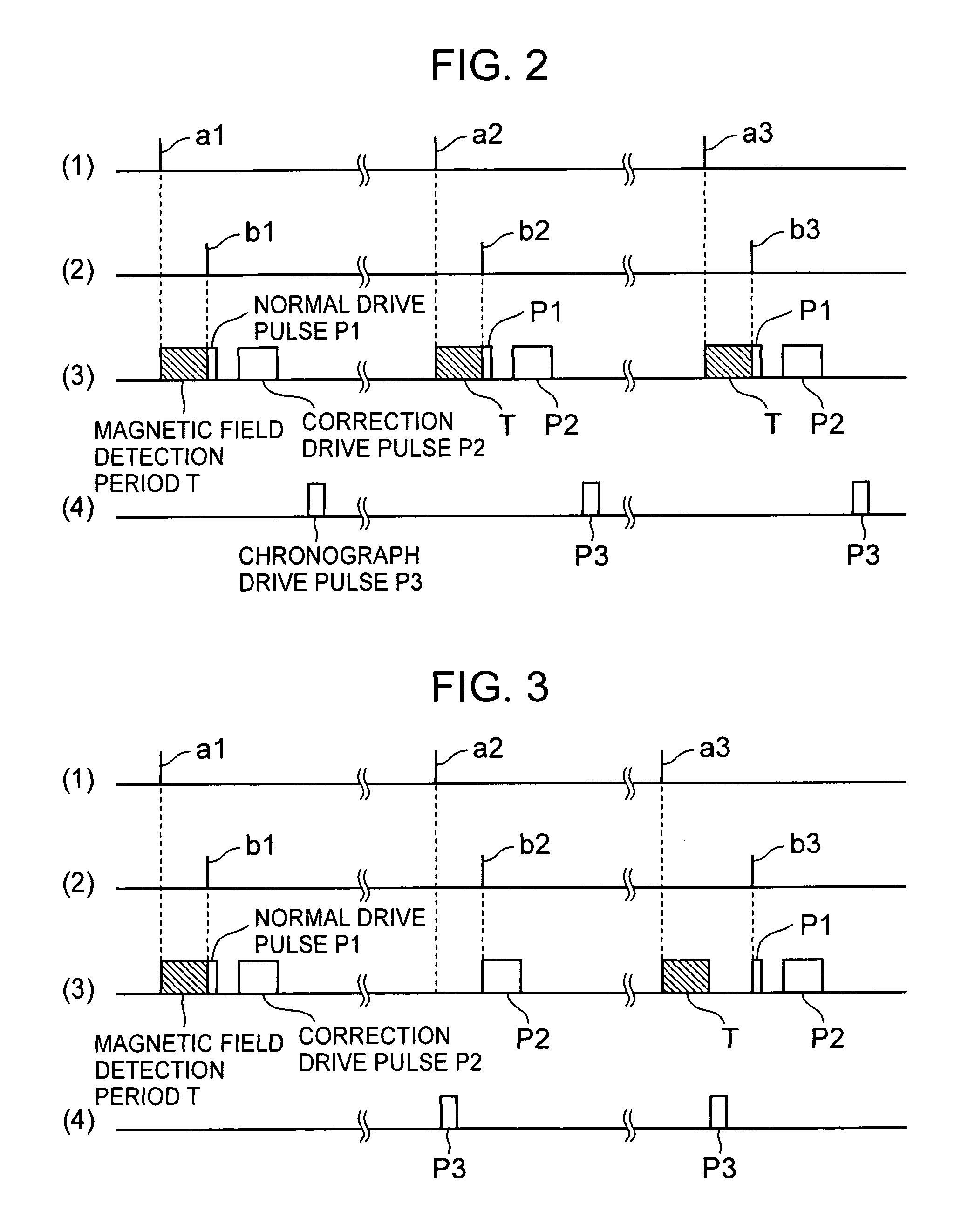
[0007]It is an aspect of the present invention to prevent a wasteful power consumption due to generation of an unnecessary correction drive pulse as a result of the chronograph drive timing and the magnetic field detection timing overlapping each other, and to prevent a deviation such as a delay in the time drive timing as a result of the magnetic field detection timing being simply delayed.
[0009]In the chronograph timepiece of the present invention, it is possible to prevent wasteful power consumption due to generation of an unnecessary correction drive pulse as a result of the chronograph drive timing and the magnetic field detection timing overlapping each other.
[0010]Further, it is possible to prevent the chronograph drive timing and the magnetic field detection timing from overlapping each other without having to delay the time hand drive timing.

Problems solved by technology

Here, in a case in which chronograph measurement is started with an arbitrary timing by the user and in which the chronograph drive timing for driving the chronograph indication motor and the magnetic field detection timing for the timepiece time motor drive circuit overlap each other, an erroneous magnetic field detection is effected under the influence of magnetic field generation due to the chronograph drive pulse, causing driving to be effected unnecessarily by the correction drive pulse; further, there is generated a deviation in the drive timing for the time indication motor due to the starting of the magnetic field detection of the time indication motor after the chronograph drive pulse.

Method used


Image

  • Chronograph timepiece
  • Chronograph timepiece
  • Chronograph timepiece

Examples


Embodiment Construction

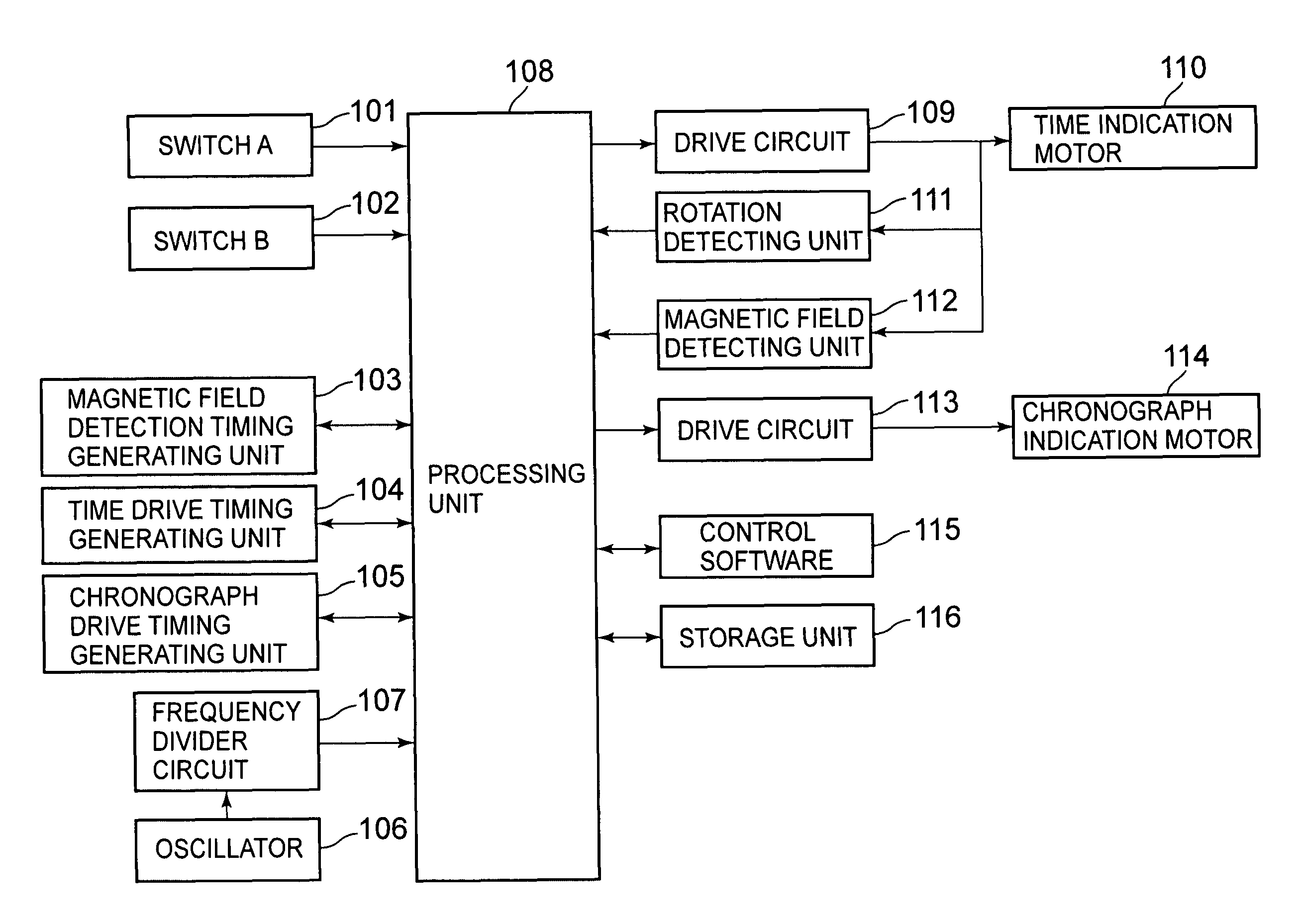
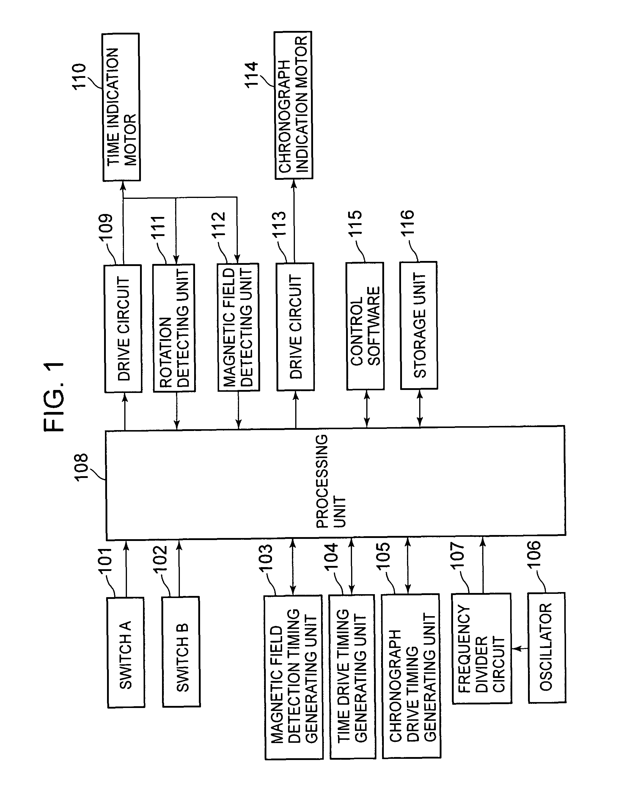
[0016]FIG. 1 is a block diagram showing a chronograph timepiece according to an embodiment of the present invention.

[0017]In FIG. 1, the chronograph timepiece includes a switch

[0018]A 101 for performing starting of a chronograph function; a switch B 102 for performing stopping / resetting of the chronograph function; a magnetic field detection timing generating unit 103 for generating a magnetic field detection timing signal indicating an external magnetic field detection timing of the chronograph timepiece; a time drive timing generating unit 104 for generating a time hand drive timing signal indicating the drive timing for time hands (e.g., an hour hand, minute hand, and second hand) (not shown); a chronograph drive timing generating unit 105 for generating a chronograph hand drive timing signal indicating the drive timing for chronograph hands (e.g., a chronograph minute hand and chronograph second hand) (not shown); an oscillator 106 generating a signal of a predetermined frequenc...


PUM


Abstract

Disclosed is a chronograph timepiece in which it is possible to prevent the chronograph drive timing and the magnetic field detection timing from overlapping each other to unnecessarily effect driving with correction drive pulses. A processing unit controls drive circuits so as to drive a time indication motor and a chronograph indication motor with a predetermined timing based respectively on timekeeping information obtained and chronograph measurement information obtained, and effects control such that a magnetic field detecting unit detects a magnetic field with a predetermined timing; when the drive timing for the chronograph indication motor and the magnetic field detection timing for the magnetic field detecting unit overlap each other, the processing unit changes the magnetic field detection timing for the magnetic field detecting unit so that the drive timing for the chronograph indication motor and the magnetic field detection timing for the magnetic field detecting unit may not overlap each other.

Description

BACKGROUND OF THE INVENTION[0001]1. Field of the Invention[0002]The present invention relates to a chronograph timepiece having a time indicating function and a time measuring function.[0003]2. Description of the Related Art[0004]There has been developed a multi-function timepiece in which a plurality of drive motors are mounted in order to individually drive a plurality of indicator hands to endow it with a time indicating function for indicating time information as a basic function and, further, with a chronograph measuring function for performing time measurement, wherein there are mounted a magnetic field detecting unit for detecting an external magnetic field around the motors and a rotation detecting unit for detecting rotation of the motors (See, for example, Japanese Patent No. 3,019,324).[0005]In the above multi-function timepiece, the rotation detecting unit and the magnetic field detecting unit are mounted in a timepiece time motor drive circuit; when non-rotation is dete...

Claims


Application Information

Patent Timeline
Patent Type & Authority Patents(United States)
IPC IPC(8): G04B19/04G04B47/06G04F5/00G04F8/00
CPCG04C3/143G04F8/00
Inventor IHASHI, TOMOHIROOGASAWARA, KENJIKATO, KAZUOSAKUMOTO, KAZUMISHIMIZU, HIROSHITAKAKURA, AKIRANOGUCHI, ERIKOHASEGAWA, TAKANORIHONMURA, KEISHIMANAKA, SABUROYAMAMOTO, KOSUKE
Owner SEIKO INSTR INC
Learn More