Image forming apparatus

a technology of forming apparatus and forming chamber, which is applied in the direction of digital output to print units, instruments, sustainable buildings, etc., can solve the problems of power supply waste, achieve the effect of preventing wasteful power consumption, convenient timing determination, and smooth formation

Active Publication Date: 2014-06-24
SEIKO EPSON CORP
View PDF9 Cites 0 Cited by
  • Summary
  • Abstract
  • Description
  • Claims
  • Application Information

AI Technical Summary

Benefits of technology

[0007]An advantage of some aspects of the invention is to provide an image forming apparatus which can achieve energy conservation appropriately according to the usage state of the function of image formation.
[0010]In the image forming apparatus according to an aspect of the invention, the power supply unit is controlled to start the power supply to the reading unit and the display unit when the power providing instruction is provided, the reading unit and the display unit are controlled to read the image data from the storage unit and display the data on the viewing screen when the image display instruction is provided, the display unit is controlled to display the image being displayed on the formation screen when the switching instruction from the viewing screen to the formation screen is provided, the power supply unit is controlled to start the power supply to the image forming mechanism at a predetermined timing when the operation regarding the preparation for image formation is performed before the forming instruction is provided, and the image forming mechanism is controlled to form the image instructed to be formed when an image forming instruction is provided during the display of the formation screen. In this manner, it is possible to prevent wasteful power consumption resulting from the power supply to the image forming mechanism during the image display performed on the viewing screen. Furthermore, since power starts to be supplied to the image forming mechanism at a predetermined timing when the operation regarding the preparation for image formation is performed, images can be smoothly formed compared to a case where the power starts to be supplied at the timing when the image forming instruction is provided. As a result, it is possible to achieve energy conservation appropriately according to the usage state of the function of image formation. The viewing screen herein corresponds to a screen displaying images one by one to select the image desired to be edited or the image desired to be formed, and a screen sequentially and consecutively displaying the images stored in the storage unit. The formation screen corresponds to, for example, a preview screen preview-displaying the image being displayed on the viewing screen.
[0011]In the image forming apparatus according to an aspect of the invention, the power supply controller may control the power supply unit at the timing when the instruction for switching the screen from the viewing screen to a formation screen is provided, as the predetermined timing. In this way, it is possible to easily determine the timing when the power starts to be supplied to the image forming mechanism.
[0012]In the image forming apparatus according to an aspect of the invention, the main controller may control the display unit so that the formation screen can be switched to a non-formation screen including the viewing screen, and the power supply controller may control the power supply unit to stop the power supply to the image forming mechanism when the instruction for switching the screen to the formation screen is not provided over a predetermined time after the screen is switched to the non-formation screen. In this manner, even when the power temporarily starts to be supplied to the image forming mechanism, it is possible to achieve energy conservation appropriately according to the subsequent usage state of the image forming mechanism. In the image forming apparatus according to the aspect of the invention, when the instruction for switching the screen to the non-formation screen is provided while the initialization of the image forming mechanism is performed along with the starting of the power supply to the image forming mechanism, the main controller may control the display unit to switch the screen to the non-formation screen after the initialization is completed. In this manner, it is possible to prevent an unexpected problem that, for example, the mechanism stops in the middle of operation since the initialization of image forming mechanism ends halfway.
[0013]In the image forming apparatus according to an aspect of the invention, when a slide show instruction is provided as the image display instruction, the main controller may control the reading unit and the display unit to sequentially read the image data from the storage unit and display the image data on the viewing screen. In the slide show in which a plurality of images is displayed consecutively, it is not necessary to supply power to the image forming mechanism over a relatively long time; therefore, the invention can be applied thereto with great significance.
[0014]In the image forming apparatus according to an aspect of the invention, the image forming mechanism may include a discharge head in which a nozzle discharging liquid is formed, and the main controller performs the initialization of the image forming mechanism by discharging liquid from the nozzle as well as the mechanical operation of the mechanism when the power starts to be supplied to the image forming mechanism. In this manner, not only can wasteful power consumption be prevented, but also wasteful liquid consumption can be prevented; therefore further energy conservation can be achieved.

Problems solved by technology

Since it is not the case that all functions of these apparatuses are used all the time, when these apparatuses are turned on and power is supplied to respective units of these apparatuses so that all functions become usable, the power supply becomes wasteful in some cases, and thus is not preferable in terms of energy conservation.

Method used


Image

  • Image forming apparatus
  • Image forming apparatus
  • Image forming apparatus

Examples


Embodiment Construction

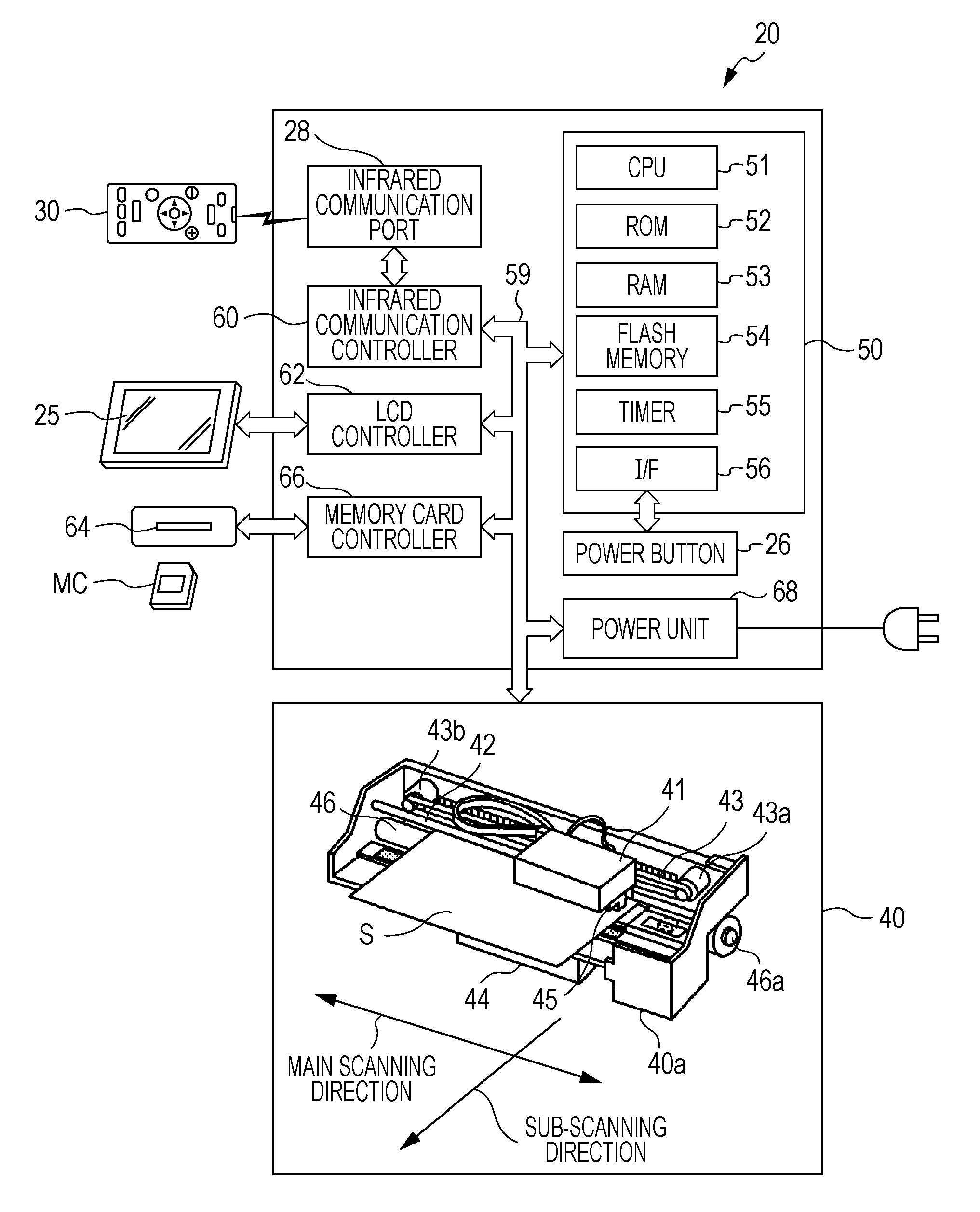
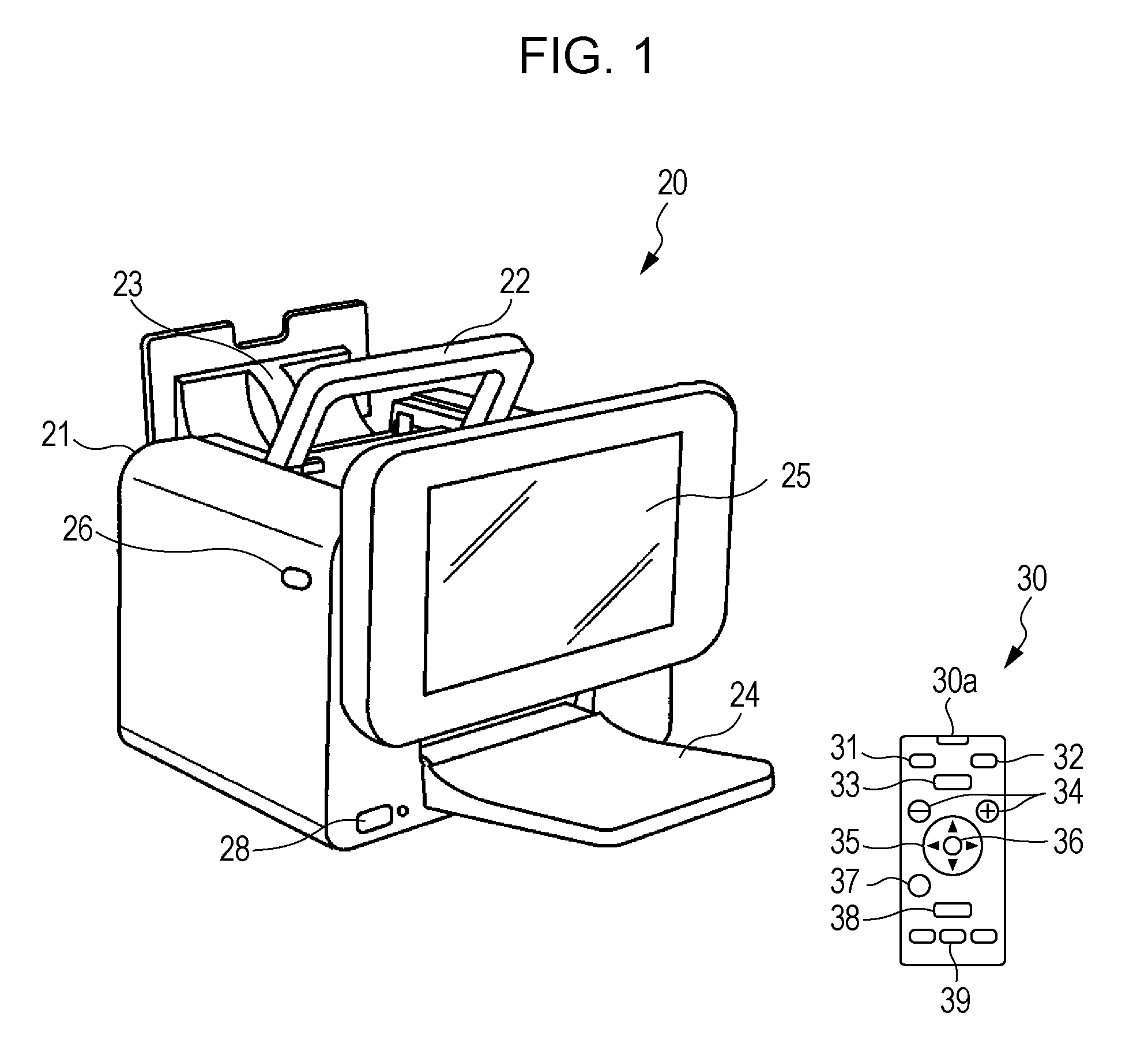
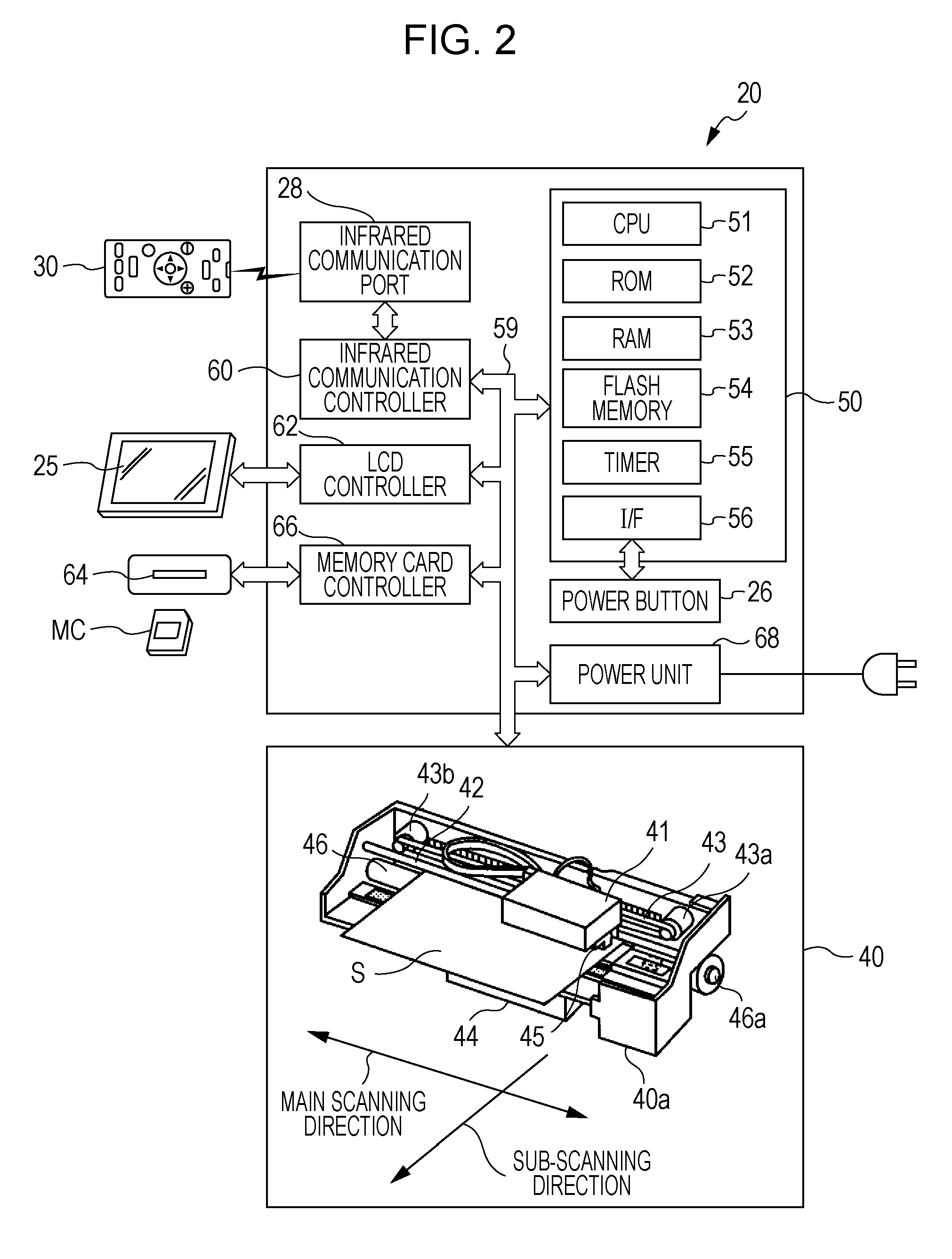
[0022]Next, the embodiment of the invention will be described based on the figures. FIG. 1 is an exterior perspective view showing the exterior appearance of a printer 20 as an embodiment of the invention, and FIG. 2 is a configuration view showing the schematic configuration of the printer 20.

[0023]The printer 20 according to the embodiment is configured as an offset printer which includes a built-in printing mechanism 40 (refer to FIG. 2) and performs printing on a sheet S of L print size or a postcard size. As shown in FIG. 1, the printer 20 includes a handle 22 provided on the upper side for carrying a body 21, an auto sheet feeder 23 automatically feeding the sheet S (refer to FIG. 2) set in the rear side of the body 21, a catch tray 24 receiving the sheet S printed by the printing mechanism 40, a liquid crystal display (LCD) 25 which is vertically slidable and used for displaying images or checking the settings during printing, and a power button 26 for turning the main power ...


PUM


Abstract

When power is turned “ON”, power starts to be supplied to a reading unit and a display unit so that images stored in a storage unit can be displayed, and when the images are instructed to be displayed, a viewing system screen is displayed. The power starts to be supplied to an image forming mechanism at a timing when an instruction for switching the viewing system screen to a formation screen, and when an instruction for forming the image being displayed on the formation screen is provided, the image is formed by the image forming mechanism. In this manner, it is possible to prevent wasteful power consumption caused when the power is supplied to the image forming mechanism while the image is displayed on the viewing system screen.

Description

CROSS REFERENCES TO RELATED APPLICATIONS[0001]The entire disclosure of Japanese Patent Application No. 2010-32149, filed Feb. 17, 2010 is expressly incorporated by reference herein.BACKGROUND[0002]1. Technical Field[0003]The present invention relates to an image forming apparatus which is connected to a storage unit storing image data and forms an image using image data selected from the stored image data by a user.[0004]2. Related Art[0005]As such a type of image forming apparatus, there is suggested an apparatus in the related art. When image data is not input from a host computer for a predetermined time or longer, or when a power key on an operation panel is pressed by a user, the apparatus stops power supply to a recording head or respective driving motors and switches to an energy-saving control (refer to JP-A-2004-345307, for example).[0006]To perform the energy-saving control is an important task in terms of energy conservation. Incidentally, regarding the image forming appa...

Claims


Application Information

Patent Timeline
Patent Type & Authority Patents(United States)
IPC IPC(8): B41J29/38
CPCG06F3/1229G06F3/1221G06F3/1271G06F3/128H04N1/0044Y02B60/1271Y02D10/00
Inventor IWANAGA, TSUTOMU
Owner SEIKO EPSON CORP
Why Eureka
Try Eureka