
Positioning device having two object holders

a technology of object holders and positioning devices, which is applied in the direction of cameras, maintainance and safety accessories, and large fixed members, etc., can solve the problems that the characterization of the semiconductor substrate present on the second object holders and the exposure of the semiconductor substrate present on the first object holders cannot be carried out independently from each other, and the exposure of the semiconductor substrate present on the first object holders cannot be started, so as to achieve the effect of high degree of adjustability of the object tables

Inactive Publication Date: 2008-02-05
ASML NETHERLANDS BV
View PDF16 Cites 102 Cited by
  • Summary
  • Abstract
  • Description
  • Claims
  • Application Information

AI Technical Summary

Benefits of technology

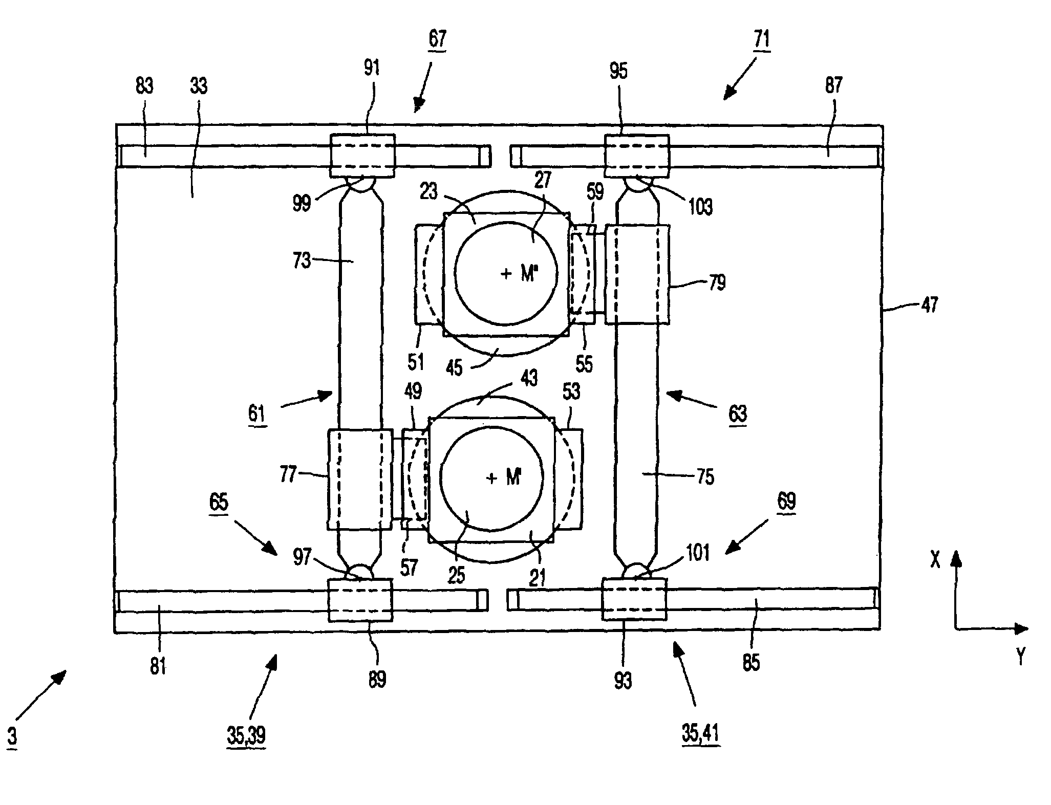
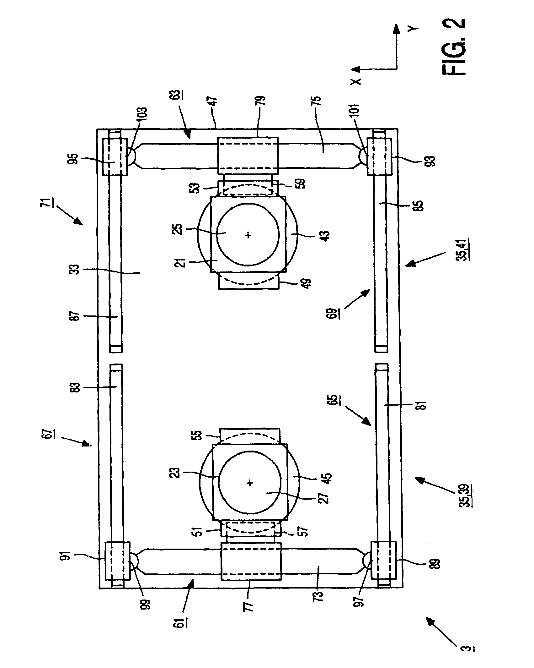
[0007]The positioning device according to the invention is for this purpose characterized in that the displacement system comprises a first displacement unit and a second displacement unit to which the first object holder and the second object holder can be coupled alternately, the first displacement unit being suitable for displacing the object holders from the first position into an intermediate position between the first position and the second position, and the second displacement unit being suitable for displacing the object holders from the intermediate position into the second position. As a result of the use of said first and second displacement units, a first process involving a first series of positioning steps of the first object holder can be carried out in the first position by means of the first displacement unit, and a second process involving a second series of positioning steps of the second object holder can be carried out in the second position by means of the second displacement unit simultaneously with and independently from the first process. When the first process and the second process have been completed, the first object holder is displaced by the first displacement unit from the first position into the intermediate position and the second object holder is displaced by the second displacement unit from the second position into the intermediate position. In the intermediate position, the first object holder is uncoupled from the first displacement unit and is coupled to the second displacement unit, while the second object holder is uncoupled from the second displacement unit and is coupled to the first displacement unit. Subsequently, the first object holder is displaced by the second displacement unit from the intermediate position to the second position and the second object holder is displaced by the first displacement unit from the intermediate position to the first position. Then the first process can be carried out with the second object holder in the first position and, simultaneously and independently, the second process can be carried out with the first object holder in the second position. Furthermore, as a result of the use of said two displacement units, a distance over which each individual displacement unit has to displace the object holders is reduced, so that the required dimensions of the displacement units are reduced. It is in addition prevented that the displaceable parts of the first displacement unit and the displaceable parts of the second displacement unit must be constructed so as to be capable of passing one another, which allows a comparatively simple construction of the displacement units.
[0009]A particular embodiment of a positioning device according to the invention is characterized in that the displacement units each comprise an X-motor having a first part extending parallel to the X-direction and a second part which is displaceable along the first part of the X-motor and can be coupled alternately to the first object holder and to the second object holder, and two Y-motors each having a first part extending parallel to the Y-direction and a second part which is displaceable along the first part of the relevant Y-motor, the first part of the X-motor of each displacement unit being connected to the second parts of the two Y-motors of the relevant displacement unit. Since the first part of the X-motor of each displacement unit is connected to the second parts of the two Y-motors of the relevant displacement unit, a comparatively stiff and stable support of the X-motor by the two Y-motors is obtained, which benefits the positioning accuracy of the displacement unit. Since the first displacement unit has a limited displacing range from the first position to the intermediate position and the second displacement unit has a limited displacing range from the intermediate position to the second position, the four Y-motors of the two displacement units can be arranged in two lines, which leads to a compact and simple construction of the positioning device.
[0010]A further embodiment of a positioning device according to the invention is characterized in that the first parts of the Y-motors of the two displacement units are connected to a common balancing unit which is guided relative to a base of the positioning device so as to be displaceable parallel to the X-direction and parallel to the Y-direction and to be rotatable about an axis of rotation extending perpendicularly to the X-direction and the Y-direction. Since the first parts of the Y-motors of the displacement units are connected to said common balancing unit, reaction forces of the X-motors and the Y-motors of the displacement units are transmitted via the first parts of the Y-motors to the balancing unit and are converted into displacements of the balancing unit parallel to the X-direction and parallel to the Y-direction and rotations of the balancing unit about said axis of rotation relative to the base. In this manner, a transmission of the reaction forces to the base, the guiding surface, and the object holders is prevented as much as possible, so that the positioning accuracy of the positioning device is further improved.
[0012]A particular embodiment of a positioning device according to the invention is characterized in that the object table of each of the object holders is displaceable relative to the basic part parallel to the X-direction, parallel to the Y-direction, and parallel to a Z-direction extending perpendicularly to the X-direction and the Y-direction, and is pivotable relative to the basic part about a first pivot axis extending parallel to the X-direction, a second pivot axis extending parallel to the Y-direction, and a third pivot axis extending parallel to the Z-direction. In this manner, a high degree of adjustability of the object tables relative to the basic parts is obtained.

Problems solved by technology

A disadvantage of the known positioning device and the known lithographic device is that the characterization of the semiconductor substrate present on the second object holder and the exposure of the semiconductor substrate present on the first object holder cannot be carried out independently from each other as a result of said lockstep-wise displacements of the first and the second object holder.
As a result, the exposure of the semiconductor substrate present on the first object holder cannot be started until the second object holder has reached the characterization position.

Method used


Image

  • Positioning device having two object holders
  • Positioning device having two object holders
  • Positioning device having two object holders

Examples


Embodiment Construction

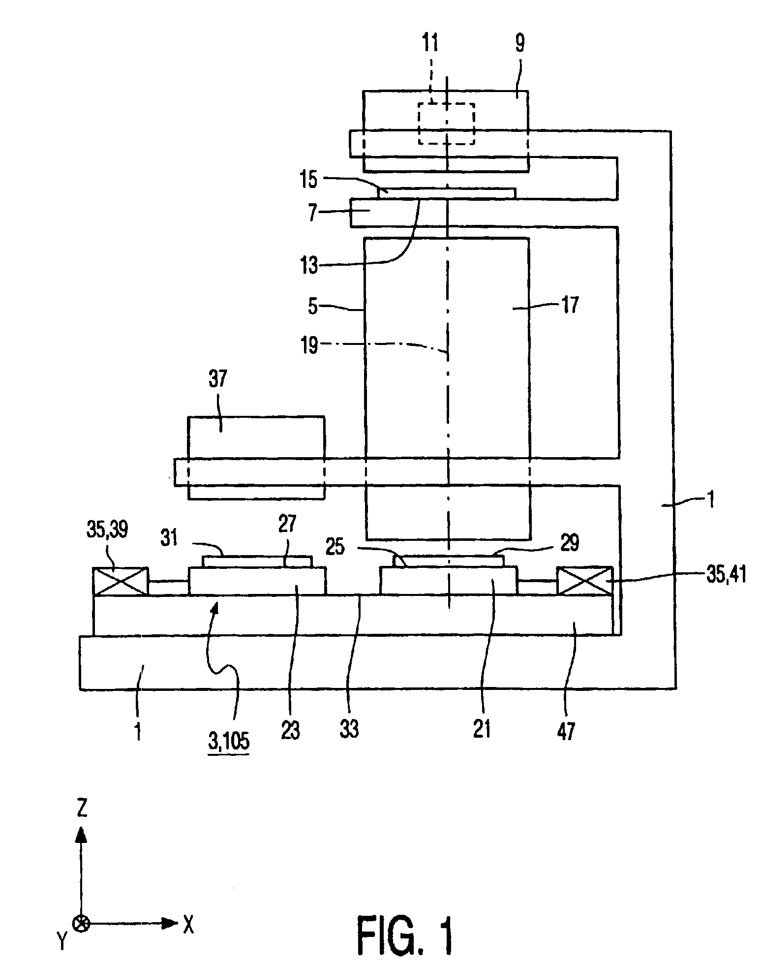
[0018]The lithographic device according to the invention shown diagrammatically in FIG. 1 is used for the exposure of semiconductor substrates in the manufacturing process of integrated semiconductor circuits and comprises a frame 1 which supports in that order, as seen parallel to a vertical Z-direction, a positioning device 3 according to the invention, a focusing unit 5, a mask holder 7, and a radiation source 9. The lithographic device is an optical lithographic device whose radiation source 9 comprises a light source 11. The mask holder 7 comprises a support surface 13 which extends perpendicularly to the Z-direction and on which a mask 15 can be placed comprising a pattern or a sub-pattern of an integrated semiconductor circuit. The focusing unit 5 is an imaging or projection system and comprises an optical lens system 17 having a main optical axis 19 extending parallel to the Z-direction and an optical reduction factor of, for example, 4 or 5. The positioning device 3 compris...


PUM

PropertyMeasurementUnit
displacementaaaaaaaaaa
distanceaaaaaaaaaa
reaction forcesaaaaaaaaaa

Abstract

A positioning device has first and second object holders that are guided over a guiding surface extending parallel to an X-direction and parallel to a Y-direction perpendicular to the X-direction and which are displaceable over the guiding surface from a first position into a second position by means of a displacement system. The displacement system includes a first displacement unit and a second displacement unit to which the object holders can be alternately coupled. The first displacement unit is suitable for carrying out a first series of positioning steps of the first object holder in the first position and for displacing the first object holder from the first position into an intermediate position between the first and second positions. The second displacement unit is suitable for carrying out a second series of positioning steps of the second object holder in the second position, simultaneously with and independently of the first displacement unit, and for displacing the second object holder from the second position into the intermediate position. In the intermediate position, the object holders are exchanged, after which the first series of positioning steps can be carried out by the first displacement unit with the second object holder in the first position and the second series of positioning steps can be carried out by the second displacement unit with the first object holder in the second position. The positioning device is suitable for use in a lithographic device to carry out an exposure process with a first semiconductor substrate in an exposure position and, simultaneously therewith and independently thereof, a characterization process with a second semiconductor substrate in a characterization position.

Description

BACKGROUND OF THE INVENTION[0001]The invention relates to a positioning device having a guiding surface extending parallel to an X-direction and parallel to a Y-direction, a first object holder and a second object holder which are each guided over the guiding surface and are each displaceable parallel to the X-direction and parallel to the Y-direction from a first position into a second position, and a displacement system for displacing the first object holder and the second object holder over the guiding surface.[0002]The invention further relates to a lithographic device provided with a radiation source, a mask holder, a focusing unit having a main axis, a characterization unit, and a positioning device, said positioning device comprising a guiding surface extending parallel to an X-direction, which is perpendicular to the main axis, and parallel to a Y-direction, which is perpendicular to the X-direction and the main axis, a first substrate holder and a second substrate holder wh...

Claims


Application Information

Patent Timeline
Patent Type & Authority Patents(United States)
IPC IPC(8): G03B27/42G03B11/00B23Q1/62B23Q11/00H01L21/027G01B21/00G03F7/20G12B5/00H01L21/68
CPCB23Q1/621B23Q1/623B23Q11/0032G03F7/70716G03F7/70733G03F7/70741G03F7/7075G03F7/709H01L21/682
Inventor KWAN, YIM-BUN PATRICKBONNEMA, GERRIT MAARTENLOOPSTRA, ERIK ROELOFVAN DER SCHOOT, HARMEN KLAASVELDHUIS, GERJAN PETER
Owner ASML NETHERLANDS BV
Learn More