Brake equalizer with housing enclosing piston and shock absorber

a technology of piston and shock absorber, which is applied in the direction of brake cylinders, braking systems, braking components, etc., can solve the problems of inability to equalize, large overall length and weight, and slow reaction time, and achieve the effect of reducing the overall length of inventive brake equalizer

Inactive Publication Date: 2003-07-01
SPERO THEODORE P
View PDF7 Cites 3 Cited by
  • Summary
  • Abstract
  • Description
  • Claims
  • Application Information

AI Technical Summary

Benefits of technology

The invention is an improved brake equalizer apparatus for equalizing fluid pressure and damping shock waves or pressure surges in fluid lines of a fluid pressure-actuated system, such as a hydraulic brake system. The inventive apparatus has a shorter reaction time than a conventional brake equalizer, and can be manufactured with smaller overall length and weight.
The inventive brake equalizer does not employ any seal (such as an O-ring seal) between the piston and the surrounding housing along which the piston slides, thus eliminating friction that would otherwise be present between such a seal and the housing as the piston slides along the housing. Besides reducing the reaction time of the brake equalizer (by reducing the piston assembly's sliding friction), elimination of seals from around the inventive piston also eliminates the need for providing oil in the volume between the sides of the piston / shock absorber assembly and the surrounding housing.
The inventive piston design allows the overall length of inventive brake equalizer to be reduced. The inventive piston design enables a preferred embodiment of the brake equalizer's housing (including body and cap portions) to have a length of 4.2 inches or even less (in contrast with the housing of U.S. Pat. No. 4,166,655 which has a preferred length of 6.4 inches).
The inventive brake equalizer design eliminates the need for a metal plate to be bonded to the elastic diaphragm which separates the piston from the variable-pressure fluid (whose pressure is to be equalized). A preferred embodiment of the inventive brake equalizer includes a screen positioned between the diaphragm and the variable-pressure fluid, to prevent contaminants (especially sharp or abrasive particles) from reaching the diaphragm and possibly penetrating through it to the piston / absorber.

Problems solved by technology

The inventor of the present application has recognized that conventional brake equalizers have several limitations, including the following: 1. they have slow reaction time, and thus are unable to equalize rapid pressure fluctuations of the type which often occur in brake air line systems; and 2. they have large overall length and weight, which renders them impractical to use in certain applications.

Method used


Image

  • Brake equalizer with housing enclosing piston and shock absorber
  • Brake equalizer with housing enclosing piston and shock absorber
  • Brake equalizer with housing enclosing piston and shock absorber

Examples


Embodiment Construction

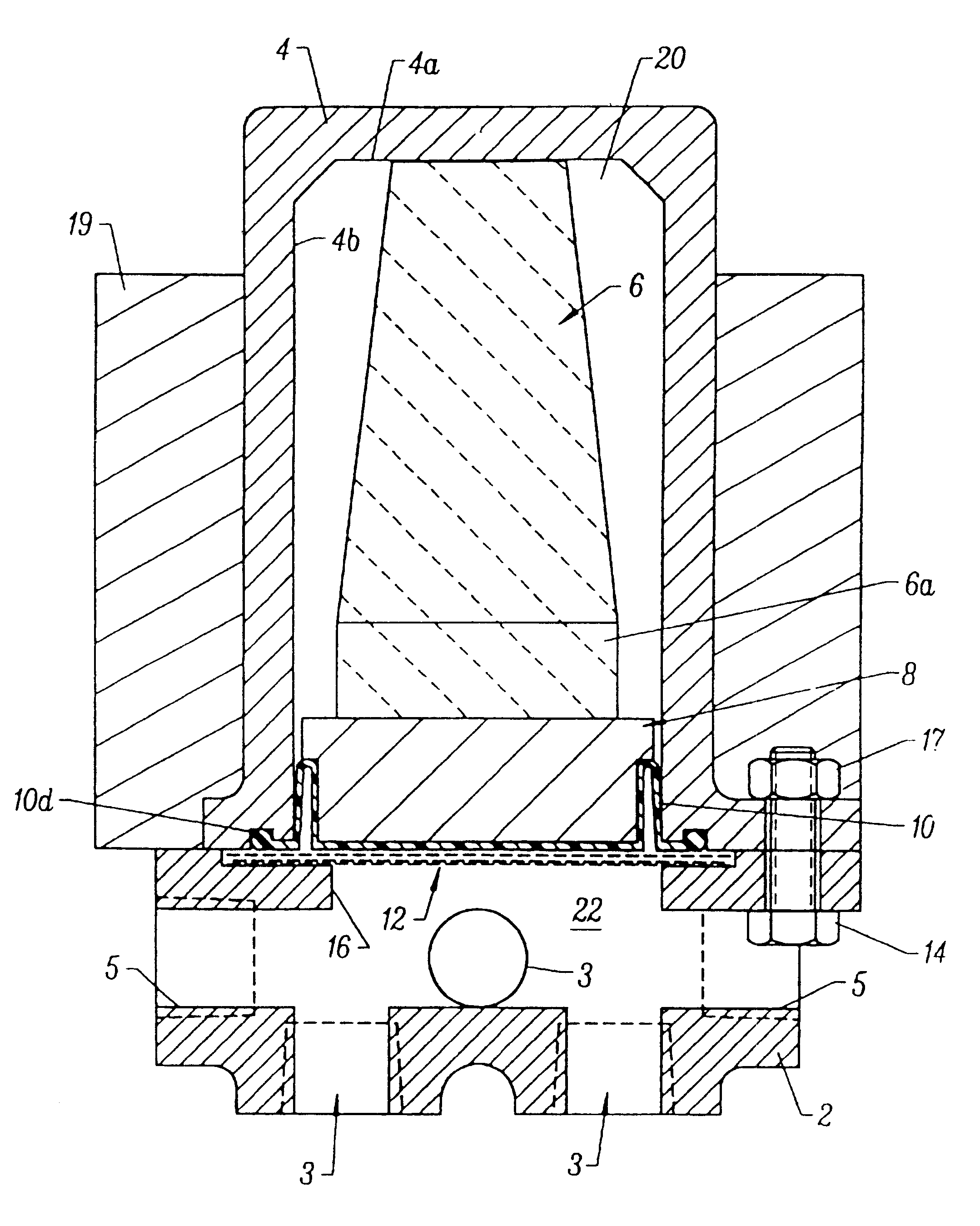
FIG. 1 is a simplified, side cross-sectional view of a preferred embodiment of the brake equalizer of the invention. The FIG. 1 apparatus includes a housing (comprising cap 2 and body 4) and a piston-shock absorber assembly (comprising piston 8 and shock absorber 6). Cap 2 and body 4 are connected together by bolts 14 and nuts 17 (one screw 14 and a mating nut 17 are shown in FIG. 1) so as to enclose volumes 20 and 22. An elastic diaphragm 10 (composed of resilient elastomer) separates volume 20 from volume 22, and seals the piston / shock absorber assembly within volume 20 from fluid in volume 22, while transmitting pressure variations in such fluid to piston 8.

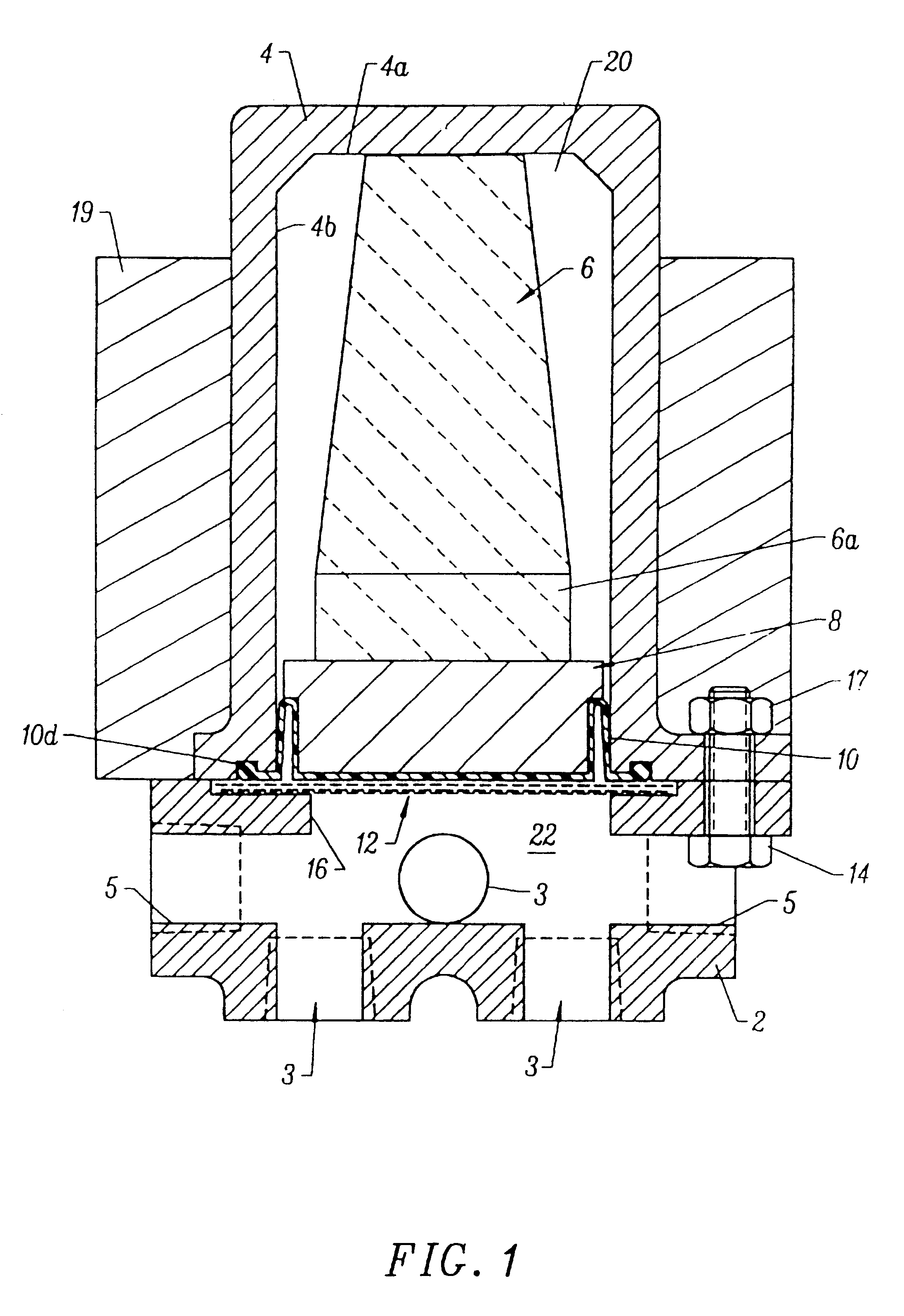
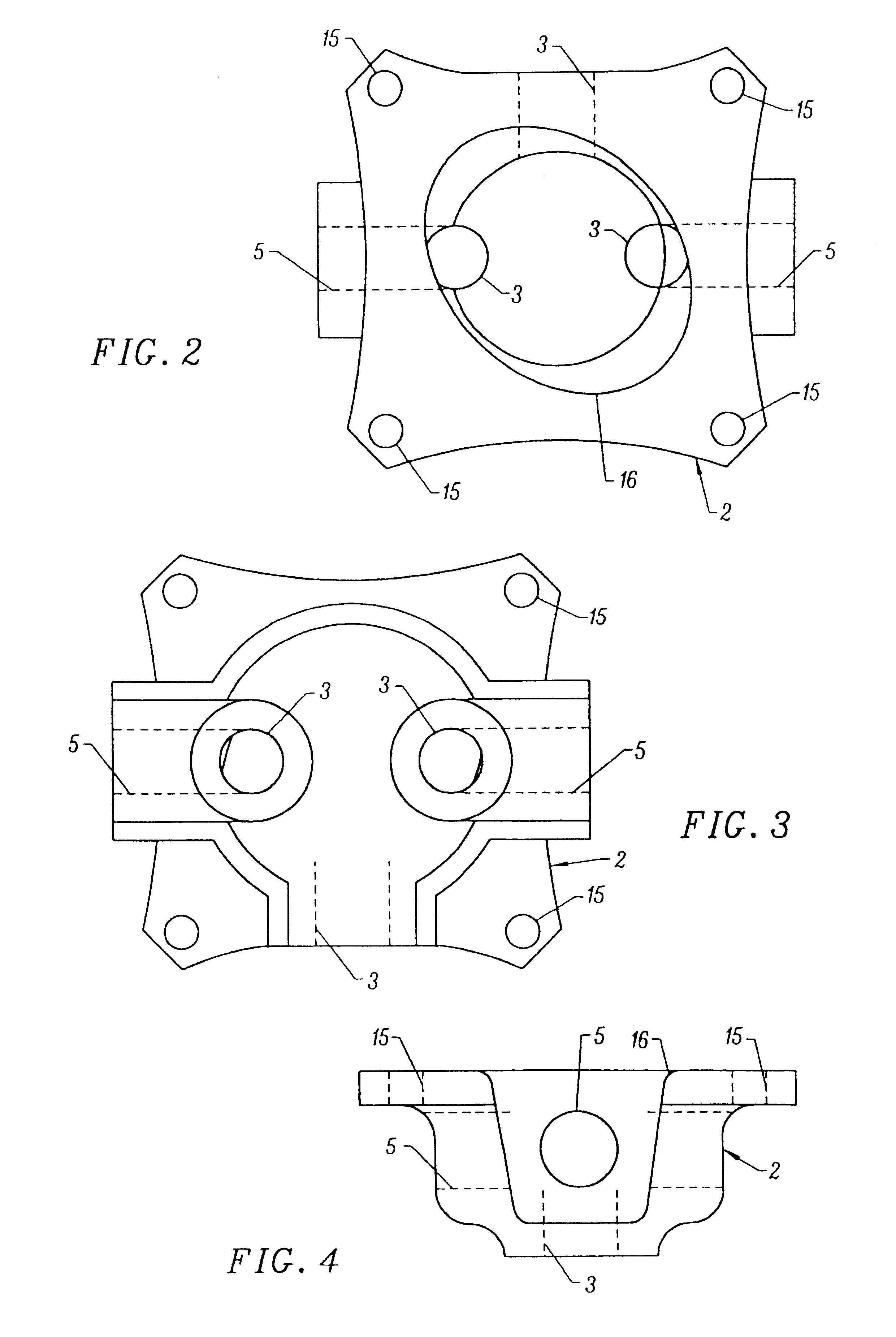
Volume 22 is an open chamber having three fluid inlets 3 (shown in FIGS. 1 through 4) and two fluid outlets 5 (shown in FIGS. 1 through 4). The FIG. 1 apparatus functions to counteract (equalize) variations in the pressure of fluid flowing within volume 22. Inlets 3 and outlets 5 are typically connected to fluid lines of a flu...


PUM


Abstract

An improved brake equalizer apparatus for equalizing fluid pressure and damping shock waves or pressure surges in fluid lines of a fluid pressure-actuated system, such as a hydraulic brake system. The apparatus has a shorter reaction time than a conventional brake equalizer, and can be manufactured with smaller overall length and weight. An important feature of the apparatus which results in reduced brake equalizer reaction time is an improved brake equalizer piston. The piston of the invention is shorter than a conventional brake equalizer piston (the ratio of the inventive piston's length to the length of the shock absorber which it abuts is substantially less than 0.5, and is preferably equal to about 0.23). The piston of the invention is also lighter than a conventional brake equalizer piston, and is preferably made of a hard, non-compressible, self-lubricating material. The brake equalizer of the invention does not employ any O-ring or other seal between the piston and the surrounding housing along which the piston slides, thus eliminating friction that would otherwise exist between such a seal and the housing as the piston slides along the housing.

Description

FIELD OF THE INVENTIONThe invention relates to brake equalizer apparatus for equalizing fluid pressure and damping shock waves or pressure surges in fluid lines of a fluid pressure-actuated system, such as a hydraulic brake system.BACKGROUND OF THE INVENTIONDevices (sometimes referred to as "brake equalizers") have been used to equalize fluid pressure and damp shock waves and pressure surges, in fluid lines of hydraulic brake systems. Brake equalizers are described in U.S. Pat. No. 4,166,655, issued Sep. 4, 1979 to the present inventor, U.S. Pat. No. 4,220,376, issued Sep. 2, 1980 to the present inventor, and U.S. Pat. No. 5,078,455, issued Jan. 7, 1992 to Washington, for example.The brake equalizer described in U.S. Pat. No. 4,220,376 includes a rigid piston 48 attached to an elastomeric shock absorber 50. Piston 48 and shock absorber 50 are enclosed within a bore in a rigid housing 56. One end of piston 48 is exposed to fluid within chamber 42, and the other end of piston 48 abuts...

Claims


Application Information

Patent Timeline
IPC IPC(8): B60T17/18B60T17/00B60T17/22B60T17/04F16L55/04F16L55/053B60T11/18
CPCB60T11/18B60T17/04B60T17/221F16L55/053
Inventor SPERO, THEODORE P.
Owner SPERO THEODORE P
Why Eureka
Try Eureka