Low-frequency pulsing sonic and hydraulic mining method

a sonic and hydraulic mining technology, applied in vibration drilling, well accessories, fluid removal, etc., can solve the problems of not being suitable for commercial subsurface submerged mining, short but effective cutting range of sonic drills and drilling machines, and relatively high purchase cost, so as to facilitate denser slurry engagement, increase recovery, and increase the effect of slurry recovery ra

Active Publication Date: 2018-06-12
GEODRILLING TECH INC
View PDF19 Cites 3 Cited by
  • Summary
  • Abstract
  • Description
  • Claims
  • Application Information

AI Technical Summary

Benefits of technology

The patent describes an improvement to a sonic drilling system by adding a high-pressure, high-volume water pump and a plurality of sonic rods to the system. The sonic rods are connected to a rotating sonic head and a casing member. The water pump provides fluid to flush cuttings up the annulus between the sonic rod and the casing member. The system also includes an eductor coupling with a plurality of upwardly directed convergent nozzles to direct fluid flow and an optional check valve to improve slurry lift and minimize blockage of slurry flow. The improvement allows for low-frequency, adjustable oscillation energy to be directed into the casing string during the pulsed jetting mining process. Overall, the improvement improves the efficiency and effectiveness of the sonic drilling system.

Problems solved by technology

Sonic drills and drilling machines have the disadvantage of a relatively high purchase cost.
For example, U.S. Pat. No. 8,006,915 to Vijay describes a surface ultra-sonic pulsed jetting hydraulic cutting apparatus with a very short but effective range for cutting stone, but which is not suitable for commercial subsurface submerged mining.
The Coakly apparatus washes cuttings from the base of the tool not allowing concentration of fragmented debris around the base of the tool and ejects them into the jetting stream and mined space.
The system is limited to mining at relatively shallow depths especially due to percussion energy dampening and has predictably low production capacity potential due primarily to the problem of retrieving dense drilling cuttings and debris with particle bridging and other issues inherent to moving slurry through conduits.
Bodine describes a recovery method facilitated by vibration helping to move slurry and oil that rises to the surface as a “floating” extraction method but does not address the difficulty in maintaining high density slurry throughout the extraction process.
Archibald teaches a pump member in a sump, which can be blocked by large boulders that can gravitate to the sump and may even trap the pump with boulders from a caving incident and can cause the loss of expensive downhole tools.
The Archibald mining tool and methods can result in boulder blockage at the sump as well as expensive loss of tooling and the system and methods do not use an eductor pump.
As a result of the lack of a viable commercial subsurface jetting system and methods, the mining industry often uses continuous-flow jetting in some mining situations where jetting can be applied, even though the continuous-flow jetting systems have relatively low mining production efficiency.

Method used


Image

  • Low-frequency pulsing sonic and hydraulic mining method
  • Low-frequency pulsing sonic and hydraulic mining method
  • Low-frequency pulsing sonic and hydraulic mining method

Examples


Embodiment Construction

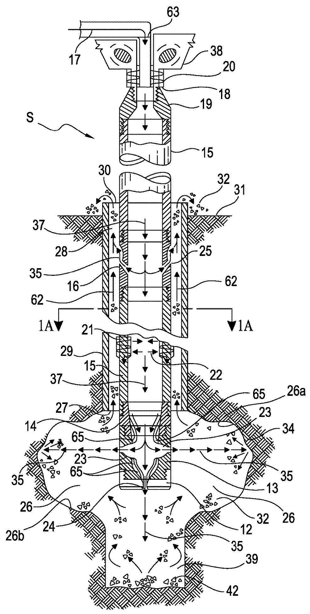
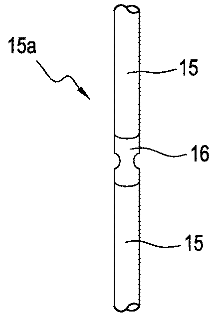
[0115]The following table lists the part numbers and part descriptions as used herein and in the figures attached hereto:

[0116]

PartNumber:Description:SInventive sonic pulsed jetting system12Pulsed jetting shoe rock bit12aUpper end of rock bit13Pulsed jetting sub-coupling13aThreaded upper end of sub-coupling13bThreaded lower end of sub-coupling14Transition rod14aThreaded upper end of transition rod14bThreaded lower end of transition rod14cUpper inner diameter of transition rod14dLower inner diameter of transition rod15Sonic rod15aSonic rod string (multiple sonic rods)16Pulsed jetting eductor coupling16aThreaded upper end of eductor coupling16bThreaded lower end of eductor coupling17Fluid column and flow direction of high-pressure andhigh-volume fluid18Sonic drill head spindle19Adapter attaching sonic rod string to the sonic drill head spindle20Sinusoidal waves propagated by oscillating parts of thesonic drill head21Sonic wave expansion and contraction of a sonic rod22Pulsing energy t...


PUM


Abstract

Enhanced method for borehole mining comprising: drilling a borehole using a low-frequency pulsing sonic, hydraulic mining system including a pulsed jet assembly; inserting casing into the borehole above target deposit depth; inserting and rotating assembly into the casing with a sub-coupling and a shoe rock bit positioned below the casing; pumping fluid into the borehole; evaluating slurry at surface; fracturing and disaggregating materials at target deposit with pulsing jets from the sub-coupling and rock bit causing light slurry to flow upwardly to the annulus between the borehole casing and the downhole assembly, then upwardly through the annulus to the surface of the borehole thereby causing heavy slurry to concentrate in a sump, located below the pulse jet rock bit; continuing to form cavity at target location; removing pulsed jet assembly from borehole; running core barrel to extract heavy slurry from sump; analyzing slurry to determine whether to continue with operation.

Description

CROSS REFERENCE TO RELATED APPLICATIONS[0001]This application is a continuation-in-part of U.S. application Ser. No. 14 / 862,122, filed Sep. 22, 2015, which claims the benefit of U.S. provisional application Ser. No. 62 / 071,420, filed Sep. 23, 2014 and each application is incorporated by reference herein in their entirety.STATEMENT REGARDING FEDERALLY SPONSORED RESEARCH OR DEVELOPMENT[0002]Not applicable.REFERENCE TO MICROFICHE APPENDIX[0003]Not applicable.FIELD OF THE INVENTION[0004]This invention relates to the field of sonic drilling systems, borehole water jet mining and sonically pulsed water jet mining systems.BACKGROUNDSonic Drilling Systems[0005]Sonic drilling systems have been used over the years primarily for borehole coring purposes. The original general sonic coring concept is credited to George Constantinesco in 1910. A sonic drill is a rotary vibratory type drill. A sonic drill looks very much like a conventional air or mud rotary drill rig. The biggest difference is in...

Claims


Application Information

Patent Timeline
IPC IPC(8): E21C45/04E21C37/12E21B43/29E21B7/18E21B21/06E21B7/24
CPCE21C37/12E21B7/24E21B7/18E21B21/065E21B43/29E21B43/38
Inventor HICE, GILBERT ALANHICE, THOMAS JOSEPH
Owner GEODRILLING TECH INC
Why Eureka
Try Eureka