
Power factor correction circuit for regulating operating frequency control circuit of power factor correction circuit and control method thereof, electronic apparatus, and power adapter

a technology of power factor correction and operating frequency control, which is applied in the direction of electric variable regulation, process and machine control, instruments, etc., can solve the problems of increasing total harmonic components, radioactive noise, network loss,

Active Publication Date: 2018-06-05
ROHM CO LTD
View PDF14 Cites 2 Cited by
  • Summary
  • Abstract
  • Description
  • Claims
  • Application Information

AI Technical Summary

Benefits of technology

The present disclosure provides a PFC circuit and control method that can prevent the operation frequency from increasing in a light load state. This circuit can set a switching point between a first mode and a second mode, and use circuit elements of different channels in a time-division manner to distribute heat generation to multiple circuit elements and avoid heat concentration. This results in improved efficiency and a reduction of heat generation.

Problems solved by technology

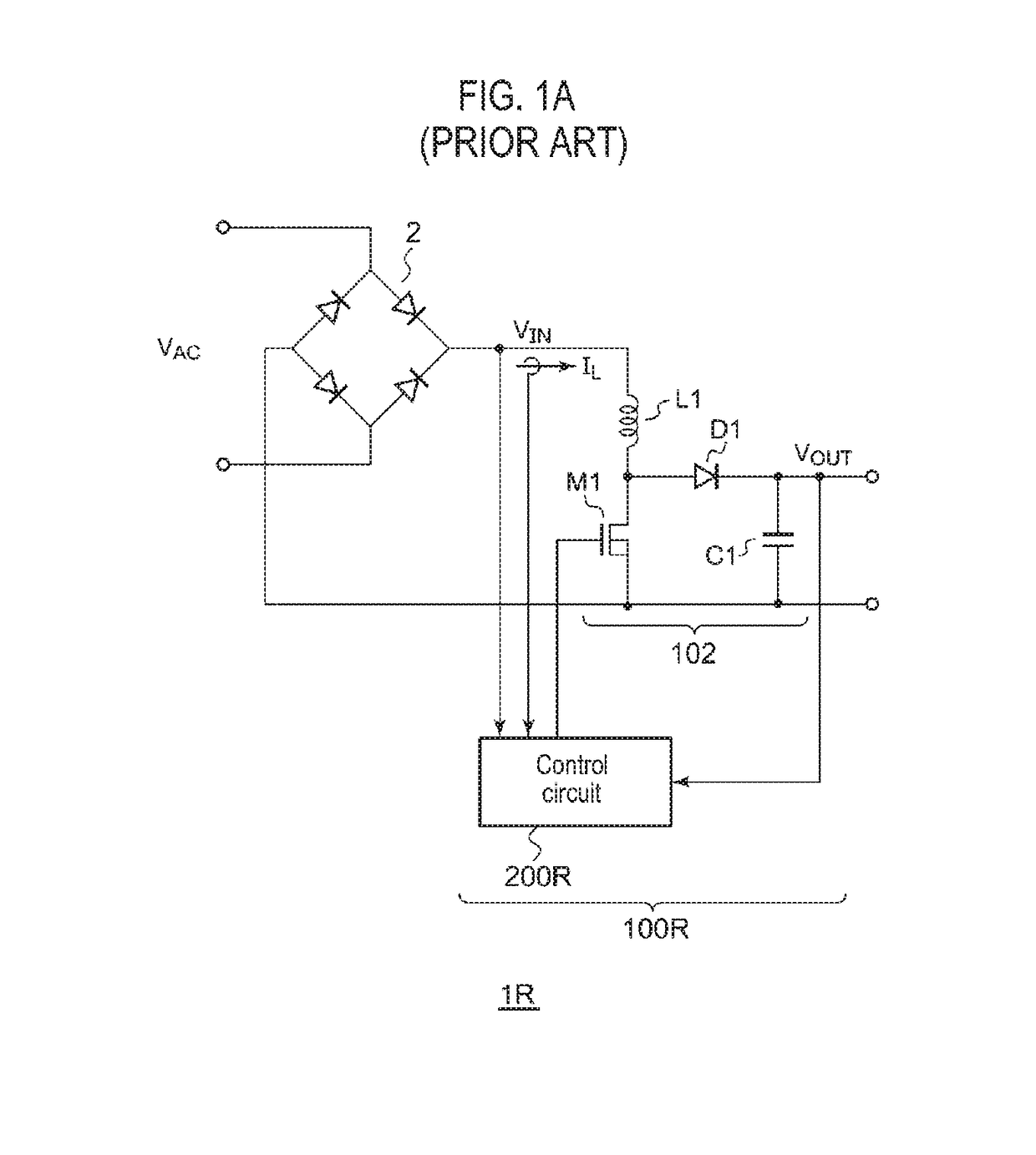
Such a current pulse causes problems such as radioactive noise, network loss and increase of total harmonic components.
Therefore, when the operating frequency f becomes too high, the PFC circuit operates in an uncontrollable region due to the response delay, which may result in a poor power factor.
In addition, an increase in the operating frequency f leads to an increase in switching loss of the switching transistor M1, which is one factor of efficiency reduction of the PFC circuit in a light load state.
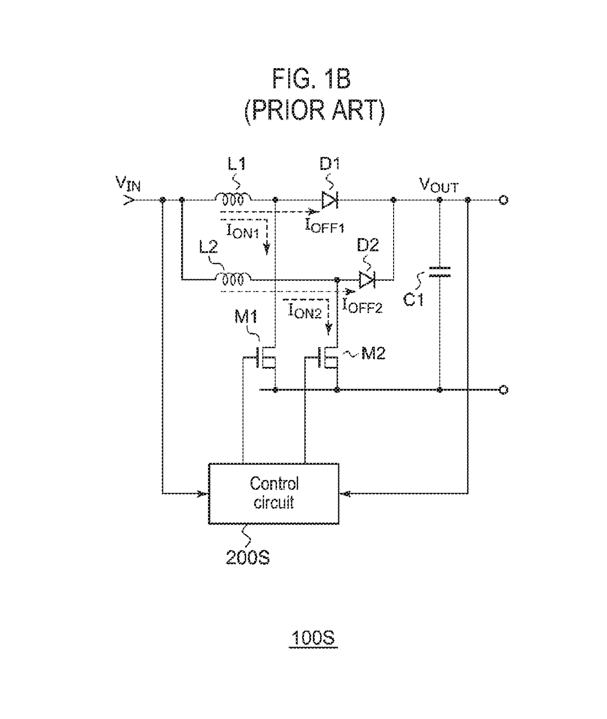
That is, according to the above-described technique, it is not possible to freely set a switching point between a one-phase operation mode (single-phase mode) and the two-phase operation mode.
Specifically, in the above-described technique, it is difficult to set the switching point within a region higher than 50% of a maximum output power in a two-phase operation mode.
Depending on applications, there are some cases where it is desired to switch a mode at any point higher than 50% of the maximum output power, in which cases it is difficult to adopt the above-described technique for such applications.

Method used


Image

  • Power factor correction circuit for regulating operating frequency control circuit of power factor correction circuit and control method thereof, electronic apparatus, and power adapter
  • Power factor correction circuit for regulating operating frequency control circuit of power factor correction circuit and control method thereof, electronic apparatus, and power adapter
  • Power factor correction circuit for regulating operating frequency control circuit of power factor correction circuit and control method thereof, electronic apparatus, and power adapter

Examples


first modification

(First Modification)

[0081]While the configuration of M(=2) channels has been described in the above embodiment, the present disclosure may be applied to a configuration of three or more channels. For an arbitrary number M of channels, the control circuit 200 may operate as follows.

(First Mode)

[0082]The pulse modulator 204 sequentially transitions the pulse modulated signals Sp1 to SpM of the M channels to an on-level with a phase difference of 360° / M.

(Second Mode)

[0083]In the pulse modulator 204, a plurality of consecutive switching periods are set as a period group TG, and, in each switching period included in the period group TG, a pulse modulated signal of one channel transitions to an on-level and then an off-level, and pulse modulated signals of the remaining (M−1) channels are kept at an off-level. In addition, during one period group TG, each pulse modulated signal transitions to the off-level at least once after transitioning to the on-level.

[0084]FIGS. 14A and 14B are wavef...


PUM


Abstract

A control circuit of a power factor correction circuit including two channels, each of which includes a switching transistor, an inductor and a rectification element, includes: an error amplifier amplifying an error of a feedback signal according to output voltage of the power factor correction circuit and target value of the feedback signal and generating an error signal; a pulse modulator generating first and second pulse modulated signals in current critical mode in response to the error signal; a first driver driving the switching transistor of first channel based on the first pulse modulated signal; and a second driver driving the switching transistor of second channel based on the second pulse modulated signal, wherein the pulse modulator switches between a first mode where phase difference between the first and second pulse modulated signals is 180° and a second mode where the first and second channels are exclusively and alternately used.

Description

CROSS-REFERENCE TO RELATED APPLICATION[0001]This application is based upon and claims the benefit of priority from Japanese Patent Application No. 2015-254128, filed on Dec. 25, 2015, the entire contents of which are incorporated herein by reference.TECHNICAL FIELD[0002]The present disclosure relates to a power factor correction circuit.BACKGROUND[0003]A variety of home appliances including a television, refrigerator, air conditioner, etc. operate with external AC power. In addition, electronic apparatuses, including laptop computers, mobile phone terminals, tablet terminals and the like, can operate with external AC power or its built-in battery is charged with the AC power. Such home appliances and electronic apparatuses (hereinafter collectively referred to as an electronic apparatus) incorporate a switching power supply for converting a commercial AC voltage to AC / DC. Alternatively, in some cases, a switching power supply may be incorporated in an external power adapter (AC adap...

Claims


Application Information

Patent Timeline
IPC IPC(8): H02M3/158H02M1/42H02M7/06
CPCH02M1/42H02M1/4225H02M7/06H02M3/1584Y02B70/126H02M2003/1586Y02B70/10H02M3/1586
Inventor OE, TAKUMIMURAKAMI, HIROYUKI
Owner ROHM CO LTD
Learn More