
Electrical box, electrical switch and electrical plug-in mechanism

a technology of electrical switch and plug-in, which is applied in the direction of coupling device connection, electrical apparatus, coupling protective earth/shielding arrangement, etc., can solve the problems of increasing the risk of electrical shock to the user/installer, increasing the installation time, and increasing the installation difficulty. , to achieve the effect of reducing installation time, increasing safety to/for user/installer, and reducing difficulty

Inactive Publication Date: 2018-06-05
DEROUSSE WELDA WILLIAM
View PDF18 Cites 5 Cited by
  • Summary
  • Abstract
  • Description
  • Claims
  • Application Information

AI Technical Summary

Benefits of technology

[0011]The newly improved electrical box, electrical switch and electrical plug-in mechanism is more user / installer friendly, which reduces installation time and in return reduces the difficulty and increases safety to / for user / installer installing / replacing electrical boxes, electrical switches or electrical plug-ins.
[0012]In brief, an improved electrical box, electrical switch and electrical plug-in mechanism design allows the user / installer to install / replace an electrical switch or an electrical plug-in, reducing exposure to the existing electrical wires, increasing safety to the user / installer during installation, while reducing / decreasing, risk of shock and / or death. Thus making the installation / replacement of an electrical box, electrical plug-in or electrical switch safe, fast and easy for the user / installer.

Problems solved by technology

Current installations of electrical boxes with electrical switches or electrical plug-ins are unsafe to the user / installer via existing electrical box design(s), fastened by screw(s) and exposed wires to the user / installer.
Conventional electrical boxes consist of exposed electrical wiring connections, increasing the risk of electrical shock to the user / installer, improvements to an electrical box allows the user / installer to complete the wiring connection inside of the electrical box with socket head receptacle fastening set screws.
Conventional electrical switches and / or electrical plug-ins are unsafe to the user / installer, current electrical switches and / or electrical plug-ins are supplied with fastening screws, which increases installation time and in return exposing electrical wiring to the user / installer during installation.

Method used


Image

  • Electrical box, electrical switch and electrical plug-in mechanism
  • Electrical box, electrical switch and electrical plug-in mechanism
  • Electrical box, electrical switch and electrical plug-in mechanism

Examples


Embodiment Construction

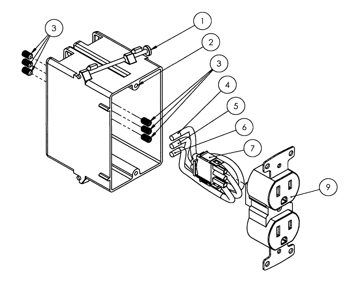
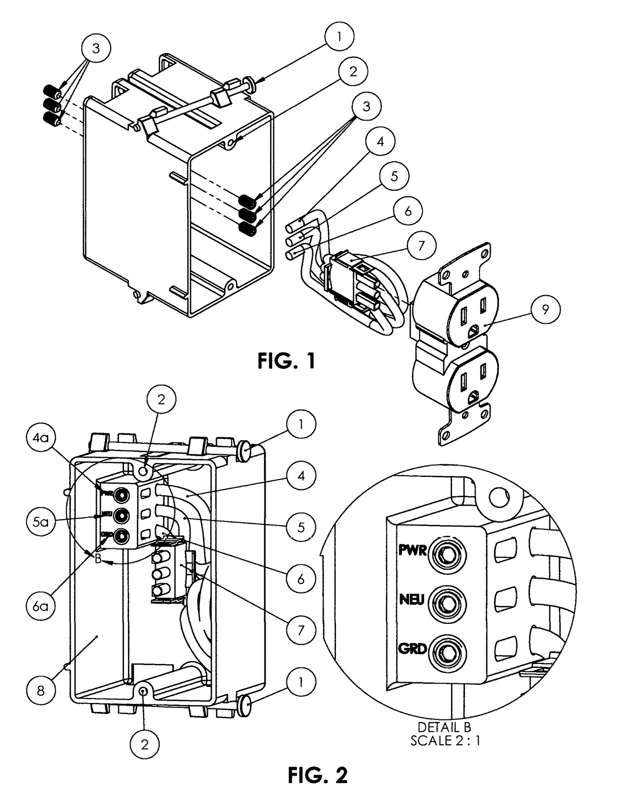
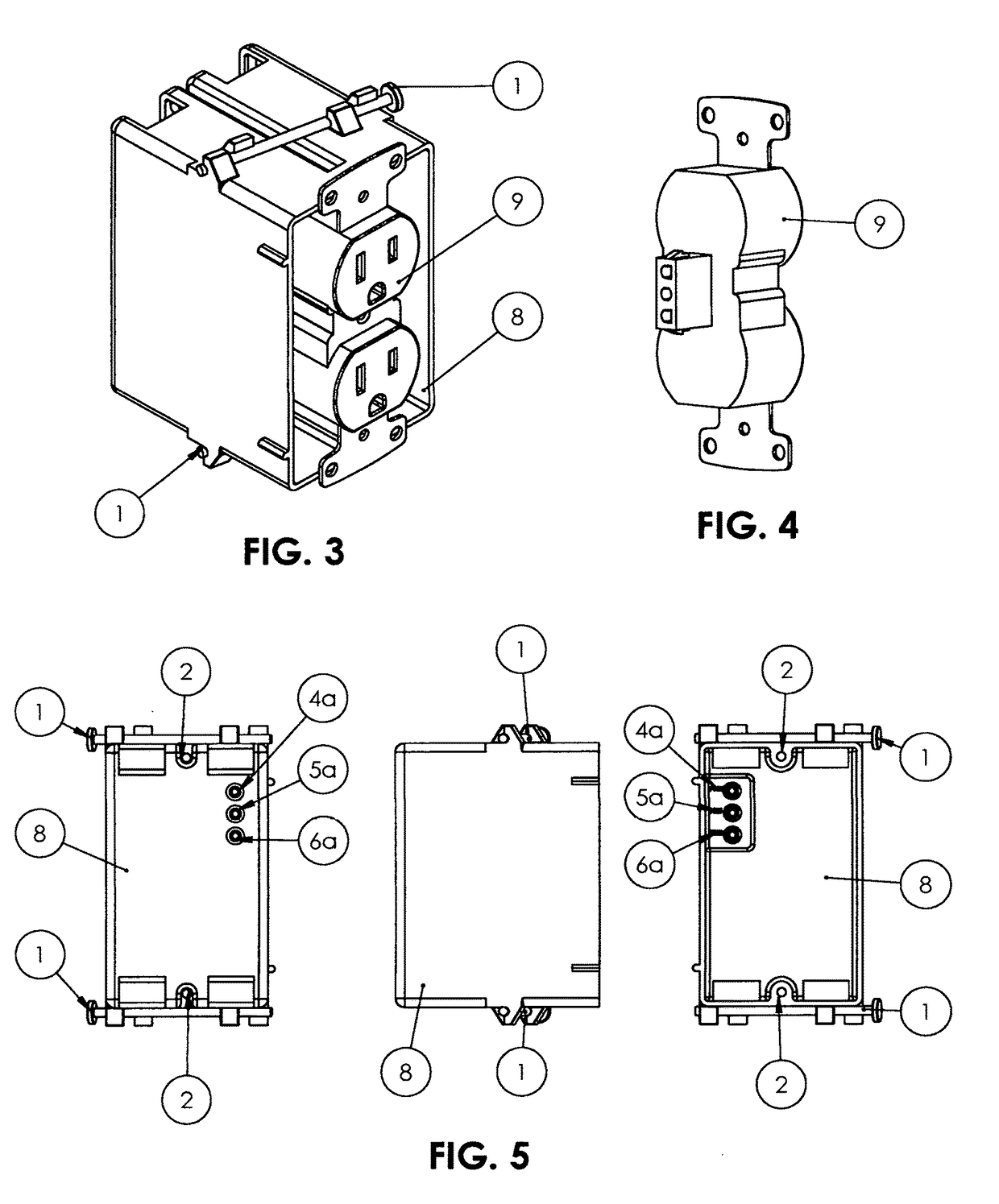
[0019]Turning to FIG. 1, an electrical box, electrical switch and electrical plug-in in accordance with the current invention, is illustrated. Electrical box, electrical switch and electrical plug-in references a 16d 3¼″ bright common framing nail 1 for attaching an electrical box 8 with installation of an electrical box 8. An electrical box 8 further includes a electrical switch / plug-in wallplate aperturere 2 to install / attach a wallplate a electrical switch and plug-in 9. Further referencing an electrical box 8 includes a power crimp housing plug 7 for quick and easy installation / replacement of an electrical switch and electrical plug-in 9. A power crimp housing plug 7 (male electrical wiring connection) includes a power / power in electrical wire 4, neutral / power out electrical wire 5 and a ground electrical wire 6, which connects to a power connector header 9 (female electrical connection) completing the electrical connection between a power crimp housing plug 7 and a power connec...


PUM


Abstract

An electrical box, switch and plug-in device, that facilitates the prompt and safe installation and maintenance of the components within an electrical box. The box includes a wiring connector, molded or affixed to an internal wall of the electrical box, for receiving external incoming power, and connects with a movable male electrical wiring connector, that can be plugged into the back of an installed electrical switch or electrical plug-in device. The mail electrical wiring connector, mounted upon its wiring, can be shifted within the box, to align it for plug-in with the identified electrical devices. The wiring connector incorporates a series of slots, such that when the various electrical wiring is connected therewith, the bare wires are concealed and secured therein, to assure safety.

Description

CROSS REFERENCE TO RELATED APPLICATIONS[0001]This application claims the benefit of U.S. Provisional Patent Application No. 62 / 391,123, filed Apr. 21, 2016.[0002]Field of classification search (174 / 50; 174 / 53; 174 / 59; 174 / 66; 174 / 520; 200 / 315; 307 / 112; 315 / 360; 361 / 42; 361 / 807; 439 / 136; 439 / 521; 439 / 535; 439 / 539; 439 / 625) International classification (B23P 11 / 00; B23P 17 / 00; B602 1 / 00; H05B 33 / 0845; H01H 1 / 36; H01H 3 / 38; H01H 9 / 02; H01H 21 / 02; H01H 21 / 025; H01H 23 / 16; H01H 33 / 72; H01H 33 / 182; H01H 47 / 00; H01H 47 / 22; H01H 50 / 16; H02B 1 / 24; H02G 3 / 08; H02G 3 / 10; H02G 3 / 12; H02G 3 / 14; H02G 3 / 18; H02G 3 / 086; 4 / 42; H05K 5 / 00; H05K 5 / 03; H05K 13 / 00; H05K 5 / 02; H05K 7 / 04; H05K 5 / 0217; H01R 4 / 42; H01R 13 / 58; H01R 13 / 60; H01R 13 / 66; H01R 13 / 73; H01R 13 / 74; H01R 13 / 514; H01R 13 / 703; H01R 13 / 748; H01R 13 / 6675; H01R 25 / 00; H01R 25 / 006; HR01R 13 / 154; H04N 7 / 188; G08B 13 / 24; G08B 13 / 196; G11C 11 / 419) U.S. classification CPC (B602 1 / 00; F21V 23 / 00; F21V 23 / 001; F21V 23 / 02; F21V 23 / 04; F21V 23 / 023;...

Claims


Application Information

Patent Timeline
Patent Type & Authority Patents(United States)
IPC IPC(8): H01R13/60H01R13/639H01R13/645H02G3/14H02G3/16H02G3/18H01R13/652H01R25/00
CPCH01R13/6395H01R13/6456H01R13/652H01R25/006H02G3/14H02G3/16H02G3/18
Inventor DEROUSSE, WELDA WILLIAM
Owner DEROUSSE WELDA WILLIAM
Learn More