
System and method for laser scribing a solar panel and the solar panel

Inactive Publication Date: 2018-05-29
THE CHINESE UNIVERSITY OF HONG KONG
View PDF5 Cites 2 Cited by
  • Summary
  • Abstract
  • Description
  • Claims
  • Application Information

AI Technical Summary

Benefits of technology

The present patent application describes a system and method for laser-scribing solar panels that allows for the creation of patterns that improve the efficiency and appearance of solar panels. The system can be used on thin film solar panels made from CIGS, CZTS, CdTe solar cells, or rigid or flexible substrates such as glass or polyimide. The laser-scribing process can result in high efficiency solar panels, with modules fabricated on glass reaching 14.25% efficiency and modules on polyimide reaching 10.35% efficiency. Overall, the system and method for laser-scribing solar panels described in this patent application offer a flexible way to create more attractive and efficient solar panels.

Problems solved by technology

However, the P1, P2 and P3 lines are usually simple straight lines separated side by side in the prior art, which cannot satisfy the market requirements for product customization.
In addition, for the thin film solar panel on a flexible substrate, such as polyimide, it is very difficult to scribe patterns by using conventional laser-scribing techniques.
Because even if the P1 line on a Mo back contact layer is straight at first, it will bend in the followed processes since the substrate may suffer from the thermal distortion.

Method used


Image

  • System and method for laser scribing a solar panel and the solar panel
  • System and method for laser scribing a solar panel and the solar panel
  • System and method for laser scribing a solar panel and the solar panel

Examples


Embodiment Construction

[0022]The present application will be further described in detail in conjunction with the accompanying drawings and embodiments. It should be understood that the specific embodiments described herein are provided to illustrate the present application, instead of limiting the present application. It also should be noted that only parts related to the present application are shown in the figures for convenience of description.

[0023]It should be noted that, the embodiments of the present application and the features in the present application, on a non-conflict basis, may be combined with each other. The present application will be further described in details below in conjunction with the accompanying drawings and embodiments.

[0024]Disclosed herein are systems and methods for laser-scribing a solar panel with arbitrary shaped patterns. According to the present application, tracing and positioning abilities of the laser are used to control the movement of the laser, so that the formed ...


PUM

PropertyMeasurementUnit
Sizeaaaaaaaaaa
Distanceaaaaaaaaaa
Brightnessaaaaaaaaaa

Abstract

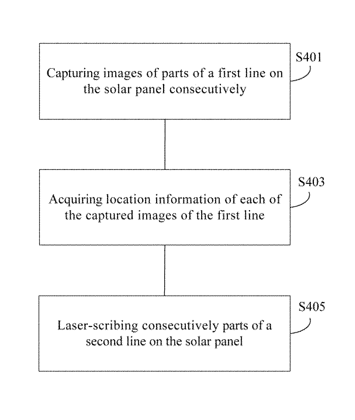
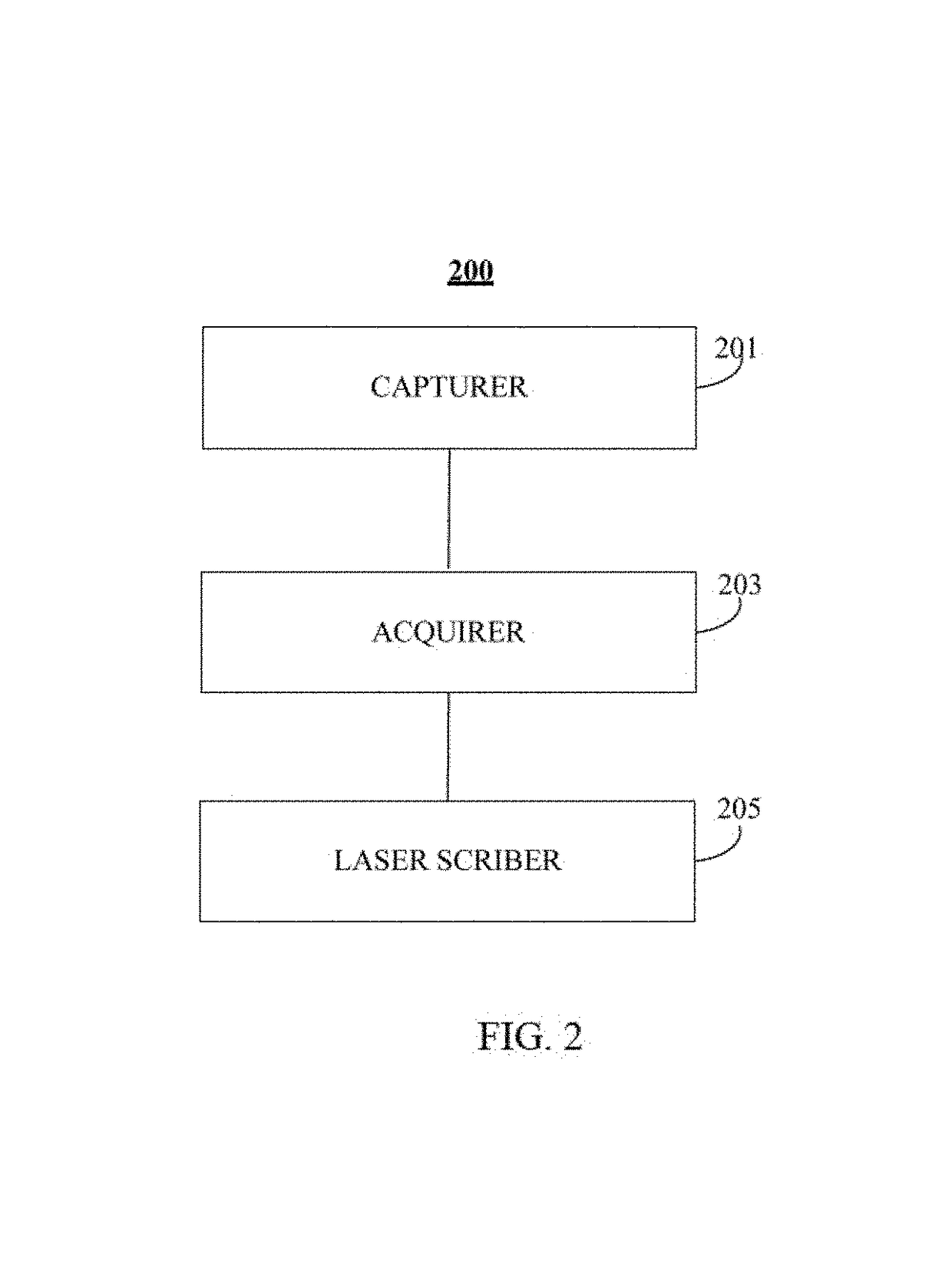
The present application discloses methods, and systems for laser-scribing a solar panel and the solar panels. The method for laser-scribing the solar panel may comprise: capturing consecutively images of parts of a first line on the solar panel, the first line having a pre-designed shape; acquiring location information of each of the captured images of the first line; and laser-scribing parts of a second line on the solar panel consecutively, according to the acquired location information of the first line, so that the scribed second line has the pre-designed shape of the first line and maintains a fixed distance from the first line.

Description

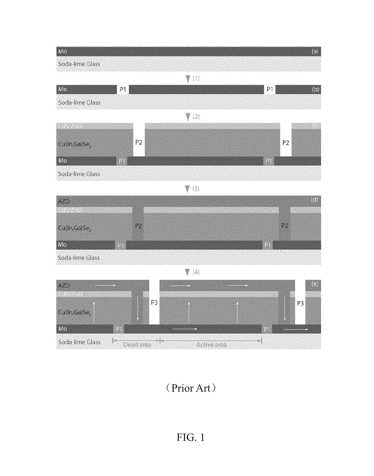
TECHNICAL FIELD[0001]The present application relates to a system and a method for laser-scribing a solar panel and the solar panel, and more specifically, to a system and a method for laser-scribing lines with arbitrary shaped patterns on a solar panel and the solar panel.BACKGROUND OF THE APPLICATION[0002]Normally, a solar panel, such as a thin film solar panel is formed by monolithically inter-connected cells using mechanical / laser scribing. FIG. 1 illustrates a conventional laser-scribing process for a CIGS solar module in the prior art. As shown in FIG. 1, there are totally three scribing lines, i.e., P1, P2 and P3 lines. Firstly, a Mo film is isolated by laser-scribing into equally spaced strips which have a width of 5 mm. The width of P1 line is about 20-70 μm. Then, a CIGS absorption layer, CdS and i-ZnO films are deposited on the Mo film. Additional P2 line is scribed right next to the P1 line to get rid of CIGS, CdS and i-ZnO films. The width of the P2 line is about 30-100 ...

Claims


Application Information

Patent Timeline
IPC IPC(8): H01L21/00G06T7/73G06T7/00B23K26/359H01L23/544H01L21/67B23K26/00H04N5/372H01L31/18B23K101/36
CPCH01L21/67282H01L23/544B23K26/0087B23K26/359G06T7/74G06T7/0006H01L2223/5446H01L31/18B23K2201/36G06T2207/20221H04N5/372G06T2207/30148B23K26/0006B23K26/083B23K26/0622B23K2103/54B23K2101/40B23K2103/172H01L31/0463Y02E10/50G06T7/0004G06T7/73B23K2101/36
Inventor ZHANG, XIAOFUYANG, SHIHANGGAO, JINLONGZHU, JIAKUANWANG, KEFANXIAO, XUDONG
Owner THE CHINESE UNIVERSITY OF HONG KONG
Learn More