
Flexible display device and computer with sensors and control approaches

a display device and computer technology, applied in the field of flexible display devices and computing devices, can solve the problems of hard to move documents from one surface to the other, interfaces have barely found their way into everyday workspaces, and devices are not bound, so as to improve the useability of visual information, reduce the reachability, and improve the presentation

Inactive Publication Date: 2018-05-01
STROETMANN CHRISTIAN
View PDF16 Cites 30 Cited by
  • Summary
  • Abstract
  • Description
  • Claims
  • Application Information

AI Technical Summary

Benefits of technology

The solution provides a brighter, more ergonomic, and versatile display experience with seamless interaction across surfaces, improved display quality, and increased usability, supporting various applications including virtual reality and augmented reality environments.

Problems solved by technology

But display devices are not bound to a flat shape.
However, despite all the advantages these interfaces have barely found their way into everyday workspaces yet.
Some reasons might be that these two areas are clearly separated, which makes it hard to move documents from one surface to the other, and that each area employs a different interaction technique.
Moreover, these systems suffer from a lack of spatial continuity.
Gaps between adjacent displays suggest isolated interactive areas, objects belonging together may be separated across gaps between display devices, and splitting objects across device borders impairs search accuracy and steering performance.
Eventually, these setups limit the applicability of for example direct manipulation, as movement trajectories are interrupted when dragging a finger or pen from screen to screen.
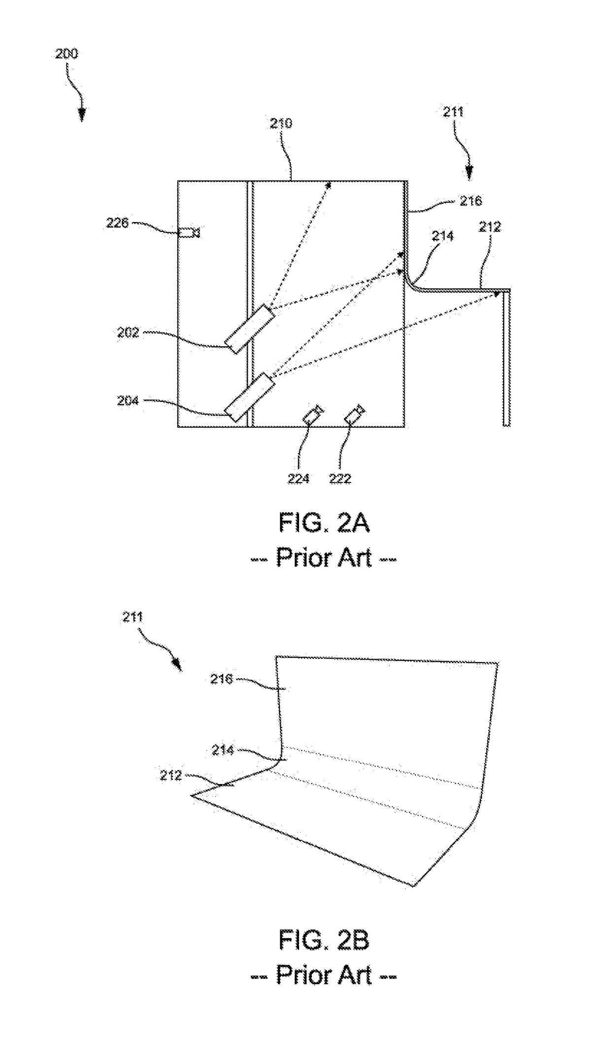
However, a problem with these display devices is that the horizontal and vertical screens are perceived as isolated areas and that by the L-shape edge a smooth, fluent transition of the displayed content cannot be realized between the vertical and horizontal screens.
But still not all problems have been solved with these curved display devices, and accordingly several areas of technical problems and general demands have been determined.
Firstly, the display devices respectively workspace environments lack of display quality.
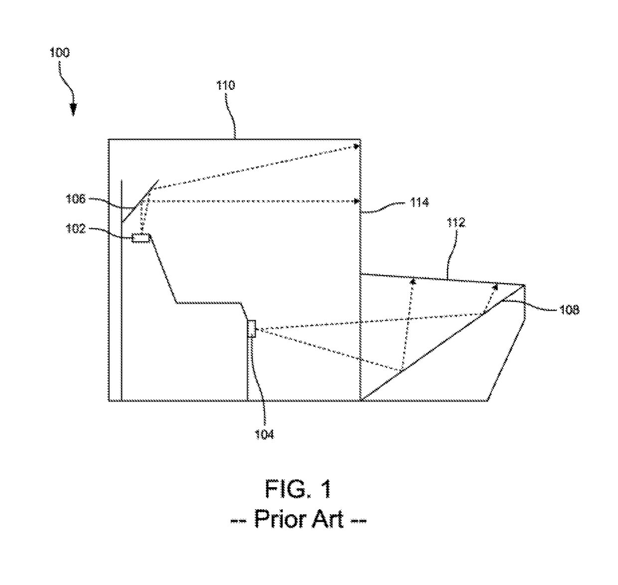
Also, the frontplane projection has the disadvantage that the user might get between the projector and the projection screen, so that parts of the projected image are projected on the user and not on the projection screen.
Secondly, solving the problem of an L-shaped display device with curved display devices leads to other problems.
For example findings of the research project “BendDesk” showed that dragging across a curve is significantly slower than on flat surfaces, a smaller entrance angle when dragging across the curve yields in a longer average trajectory and a higher variance of trajectories across users, and the curved shape of the system impairs virtual aiming at targets.
Thirdly, the display devices are large and unhandy.
In contrast, the possibilities of placing objects onto a tilted surface, even at small angles, are limited.
Thirdly, tilting the vertical surface backwards would reduce its reachability at the top, but the user should be able to sit and stand in front of the electronic display device in a comfortable position and to reach the entire input area without much effort.

Method used


Image

  • Flexible display device and computer with sensors and control approaches
  • Flexible display device and computer with sensors and control approaches
  • Flexible display device and computer with sensors and control approaches

Examples


first embodiment

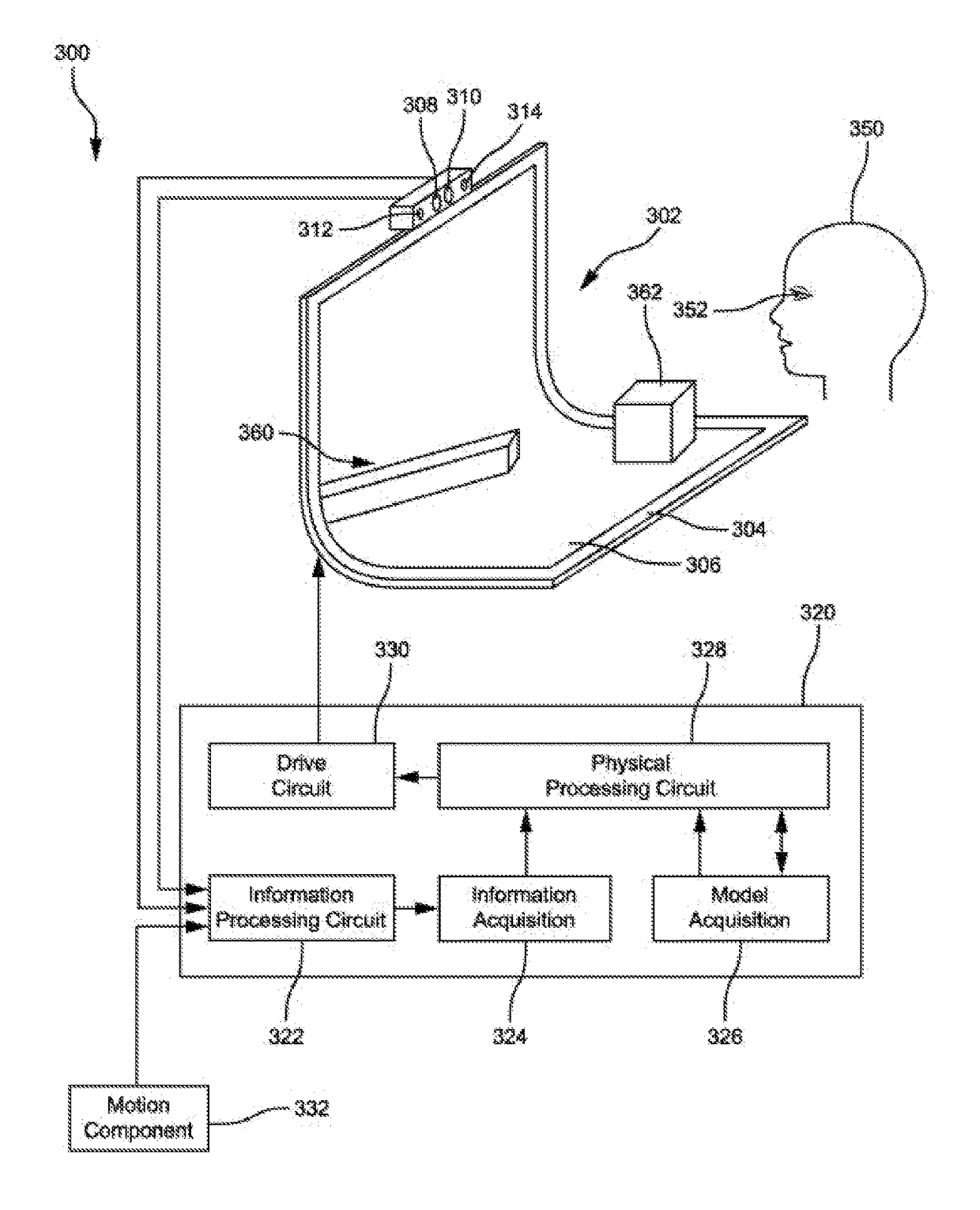
[0052]In order to provide various functionality described herein, FIG. 3 illustrates an example set of basic components of a flexible electronic visual display device 300 according to a In this example, the flexible electronic visual display device 302 features as components a flexible housing 304, a flexible capacitive or resistive multi-touch display screen 306, an image sensor or camera 308, a three-dimensional depth sensor 310, and dual-array microphones 312, 314 as information capture elements, and a control system 320, to display a three-dimensional scene 360 on the display screen to a user attempting to create, maintain, and improve a perception of depth.

[0053]The control system 320 includes an information processing circuit 322, an information acquisition component 324, a model acquisition component 326, a type of physical processing circuit 328, such as a programmable visual graphics processing unit (GPU) for example, and a drive circuit 330.

[0054]As would be apparent to o...

second embodiment

[0062]FIG. 4 illustrates an example set of basic components of a flexible electronic visual display device 400 according to a In this example, the flexible electronic visual display device 402 has a flexible housing 404, a flexible multi-touch display screen 406, four information capture elements 408, 410, 412, 414 positioned at various locations on the same side of the device as the display screen 406, a projector device 416, and a control system 420 enabling the display device to capture sensor information about a user of the device during typical operation where the user is at least partially in front of the flexible electronic visual display device, and to project images on the display screen or / and on an arbitrary object 462 put on the horizontal surface of the electronic device.

[0063]The control system 420 includes an information processing circuit 422, an information acquisition component 424, a model acquisition component 426, a type of physical processing circuit 428, such...

third embodiment

[0066]FIG. 5 illustrates an example set of basic components of a flexible electronic visual display device 500 according to a In this example, the flexible electronic visual display device 502 has a flexible housing 504, a flexible multi-touch display screen 506, four information capture elements 508, 510, 512, 514 positioned at various locations on the same side of the device as the display screen 506, a three-dimensional scanner device 518, and a control system 520 enabling the display device to capture sensor information and to scan and digitalize an arbitrary object 562 put on the horizontal surface of the electronic device.

[0067]The control system 520 includes an information processing circuit 522, an information acquisition component 524, a model acquisition component 526, a type of physical processing circuit 528, and a drive circuit 530. The four image sensors 508, 510, 512, 514 and the control system 520 work together in the same way as described in relation with the secon...


PUM


Abstract

Embodiments of a flexible electronic visual display device and a flexible mobile computer having such a display device are disclosed. The basic electronic visual display device comprises a flexible display device, at least one control system, at least one three-dimensional sensor, a flexible housing containing the electronic components, and an adjustment means for the housing. In some embodiments, the flexible display device can have additional sensors of various types, a projector, a wireless communication interface, and a wireless power supply. For independent use some embodiments of the flexible electronic visual display device can also comprise an electronic module including at least one processor and at least one data memory, and also at least one electrical energy storage device being contained in the housing as well. This permits the flexible electronic display device to provide a broad range of functionalities and application possibilities, and to assume novel functionalities and applications.

Description

CROSS-REFERENCE TO RELATED APPLICATION[0001]This application claims the benefit of the German Utility Model Application No. 20-2014-103-215.0, filed Jul. 11, 2014, and entitled “Elektronisches, visuelles Gerät, das eine flexible beziehungsweise biegbare Vorrichtung zur optischen Signalisierung von veränderlichen Informationen, ein flexibles beziehungsweise biegbares Gehäuse mit mindestens einem Gelenk / Scharnier and ein Regel- / Steuerungssystem besitzt”, which is hereby incorporated by reference in its entirety.BACKGROUND[0002]1. Field of the Disclosure[0003]The present application relates generally to flexible display devices and to computing devices with such a display. More particularly, the present invention pertains to stationary flexible display devices and to stationary and portable flexible computing devices with at least one flexible display screen and at least a three-dimensional sensor as well as flexible display devices[0004]2. Description of the Related Art[0005]People ar...

Claims


Application Information

Patent Timeline
Patent Type & Authority Patents(United States)
IPC IPC(8): G06F3/01G06F1/16H04N13/00
CPCH04N13/0497G06F1/1641G06F1/1652G06F1/1679H04N13/0468G06F3/017H04N13/0018H04N13/0402H04N13/044G06F1/1681H04N13/122H04N13/302H04N13/344H04N13/366H04N13/398
Inventor STROETMANN, CHRISTIAN
Owner STROETMANN CHRISTIAN
Learn More