
Downward elbow with cyclonic effect and product overflow capability

a technology of product overflow and downward elbow, applied in the field of air conveying apparatus, can solve the problems of non-uniform product distribution, potential damage to seeds and other fragile agricultural products, and damage to certain types of seeds, and achieve the effect of maximizing the filling of the tank

Active Publication Date: 2018-04-24
CNH IND CANADA
View PDF11 Cites 0 Cited by
  • Summary
  • Abstract
  • Description
  • Claims
  • Application Information

AI Technical Summary

Benefits of technology

The present invention allows seeds to spread evenly along the tank without creating any blockages. Additionally, the seeds flow into the tank without being limited by the outlet height, which maximizes tank fill.

Problems solved by technology

Grain augers, conveyor belts and similar mechanical seed handling equipment may cause damage to certain types of seeds.
The air conveying systems significantly reduce seed damage, however, the potential for damage to seeds and other fragile agricultural products remains.
Moreover, the products tend to accumulate more in some tank areas than others resulting in a non-uniform product distribution and corresponding non-uniformity of product delivery to the metering system.
Multiple outlet locations within the tank ameliorate this problem, however certain drawbacks and problems remain
The main problem is that the seeds are either hitting the tank walls at high velocity (bouncing violently, which could damage the seeds) or being carried throughout the tank by random vortices.
The random vortices disrupt the even filling of the tank.
Finally, if the operator wishes to add only a few small bags to the tank, the random filling would mean that some seed meters are not covered properly (or would starve prematurely).
This would cause errors during seeding since product could not be distributed evenly.

Method used


Image

  • Downward elbow with cyclonic effect and product overflow capability
  • Downward elbow with cyclonic effect and product overflow capability
  • Downward elbow with cyclonic effect and product overflow capability

Examples


Embodiment Construction

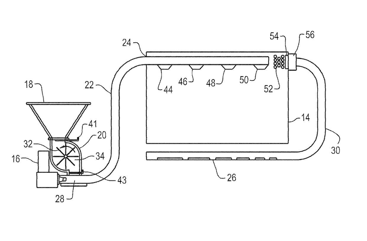
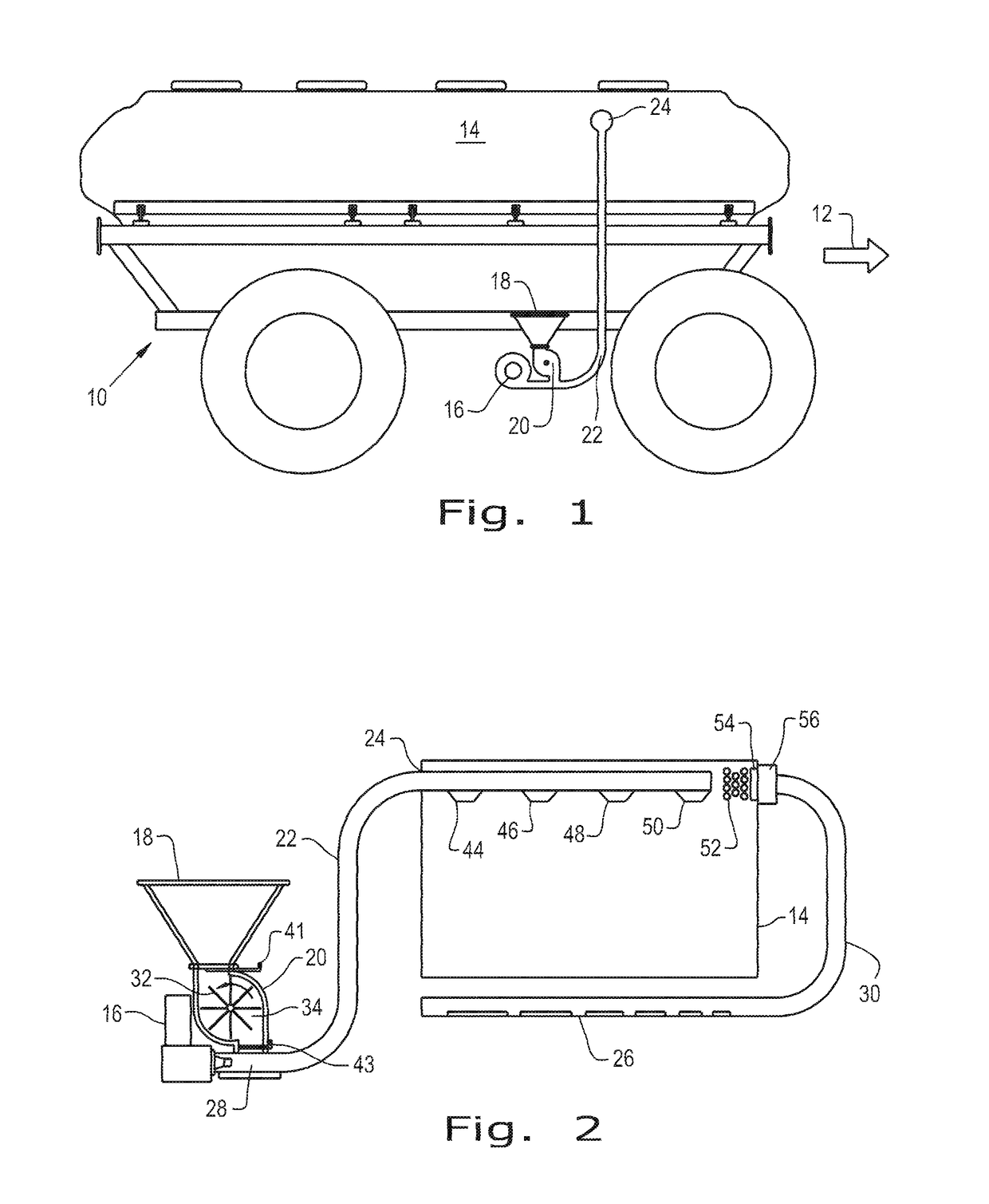
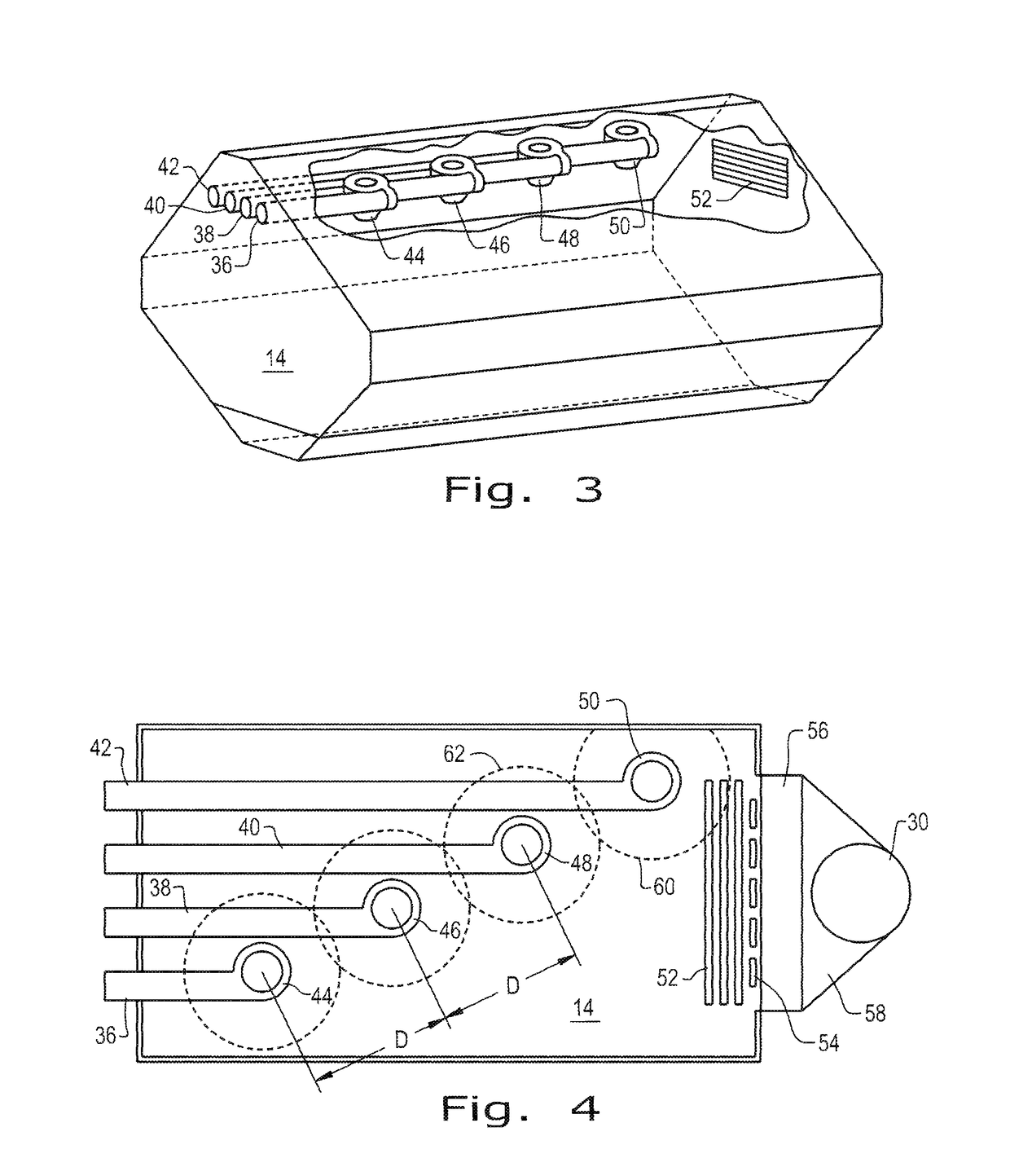
[0028]Referring now to the drawings, and more particularly to FIG. 1, there is shown an air cart 10 comprising a portion of a known pneumatic agricultural product delivery system which generally includes a traction unit (not shown) which may be coupled to air cart 10 for towing the air cart 10 in the direction of arrow 12. The system usually includes as a third unit, a utilization implement such as an air drill (not shown) for a seeding, cultivating and / or fertilizing operation. As is known in the art, the air cart 10 has one or multiple large product supply tanks 14 which store a certain quantity of the agricultural product, typically a particulate material, e.g., seed and / or inoculant, or fertilizer, and a metering system that meters the particulate material from the tank or tanks 14 to the air drill. In addition to being mechanically linked with the air drill, the air cart 10 and the air drill are interconnected by an air / product delivery system which includes a plurality of dist...


PUM


Abstract

An air system for supplying product to the product tank of an agricultural implement has an air supply and at least one elongated conduit for delivering air entrained product to the tank. There is at least one outlet in the tank formed as a hollow elbow having a generally downwardly directed outlet, a generally upwardly directed outlet and a transverse inlet coupled to the conduit. The elbow includes an upper generally cylindrical region comprising a cyclone chamber for swirling the incoming air entrained product directing at least a portion of the air flow upwardly toward the upwardly directed outlet while allowing the product to fall in a generally helical pattern through a generally frusto-conical region, whereby material migrates downwardly and air upwardly releasing the material to fall in a gentle spiral and air to exit from the upper region of the tank.

Description

BACKGROUND OF THE INVENTION[0001]1. Field of the Invention[0002]The present invention relates to farm implements and, more particularly, to an air conveying apparatus for replenishing particulate material such as seed, fertilizer, herbicide or insecticide in one or more tanks of an air seeder or other farm implement.[0003]2. Description of the Related Art[0004]Agricultural material dispensing equipment frequently employs a material tank either supported on the dispensing device or on a supply cart drawn across a field in conjunction with the dispensing device. Such arrangements are encountered on fertilizer spreaders, planters, air seeders, etc. Periodic replenishment of the material supply in the tank is required.[0005]One typical replenishing technique employs a screw auger or belt conveyor which feeds the material from a source such as a supply vehicle to the tank. Grain augers, conveyor belts and similar mechanical seed handling equipment may cause damage to certain types of see...

Claims


Application Information

Patent Timeline
Patent Type & Authority Patents(United States)
IPC IPC(8): B65G53/14B60P1/60B65G53/42
CPCB65G53/14B65G53/42B60P1/60A01C15/003A01C15/006
Inventor ROBERGE, MARTIN J.STUART, GRAHAM DOUGLAS
Owner CNH IND CANADA
Learn More