
Continuous motion linear container filler

a container and moving technology, applied in the direction of liquid handling, packaging goods type, transportation and packaging, etc., can solve the problems of not being able to fill bottles as fast, affecting the efficiency of container filling, so as to maximize the rate at which containers are filled

Active Publication Date: 2018-01-09
PSR AUTOMATION
View PDF19 Cites 4 Cited by
  • Summary
  • Abstract
  • Description
  • Claims
  • Application Information

AI Technical Summary

Benefits of technology

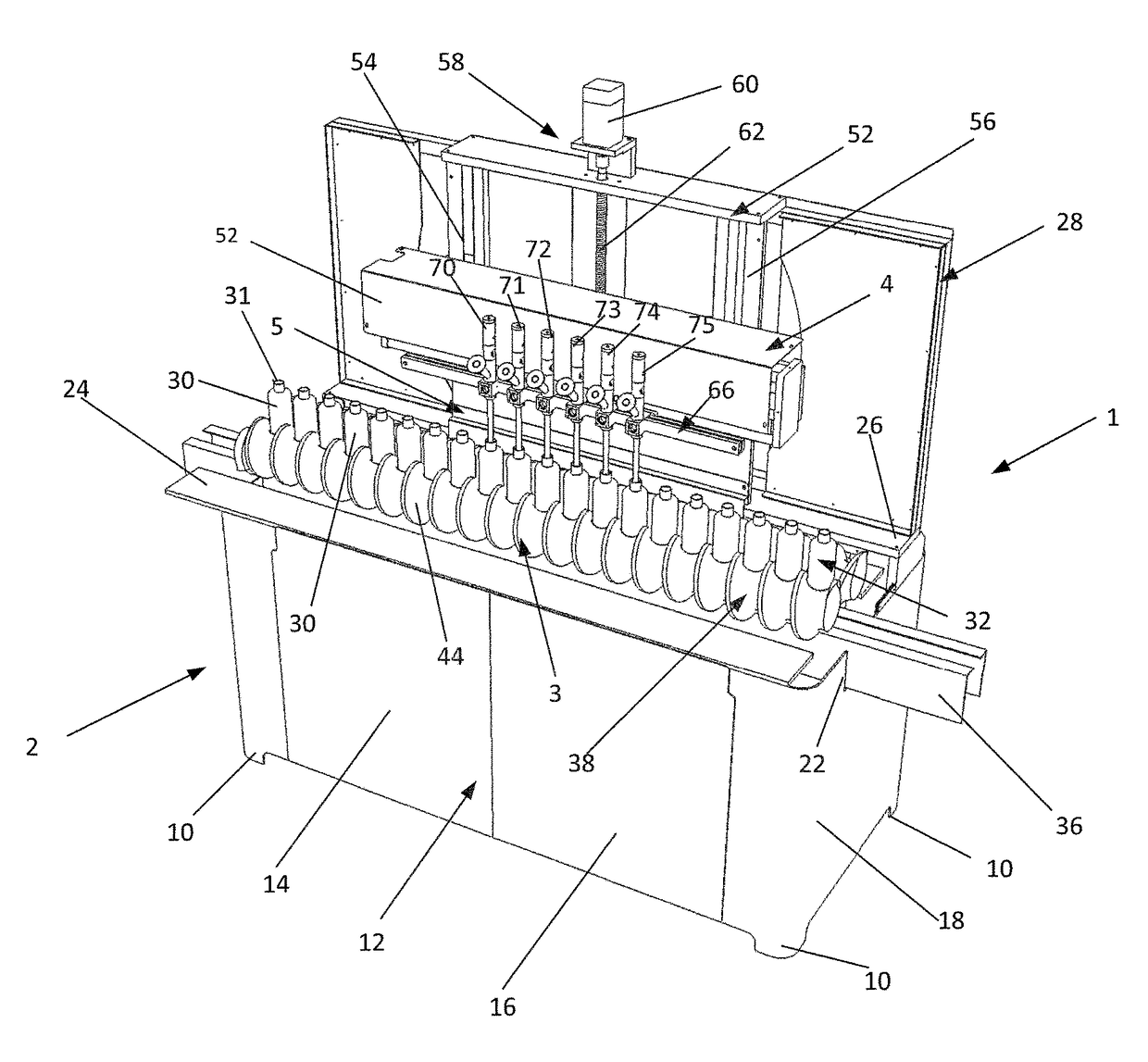
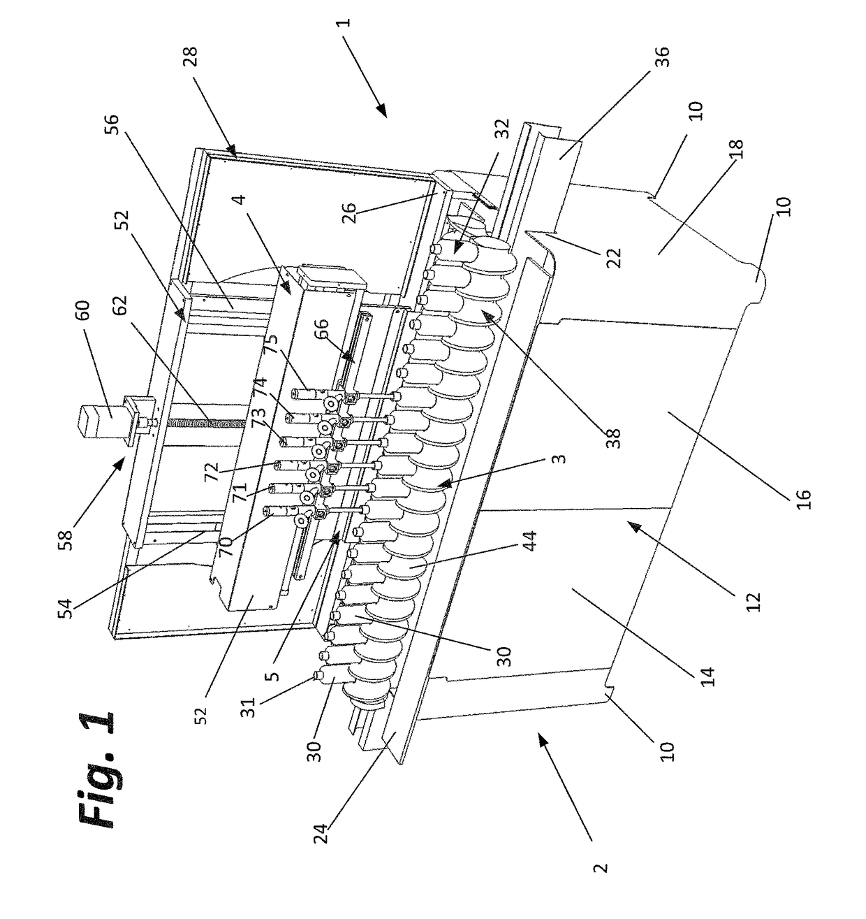
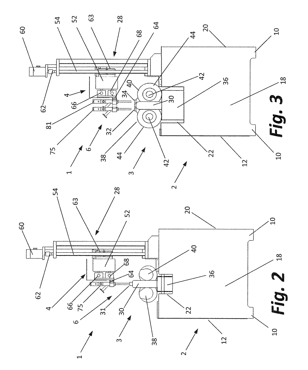
The patent describes a way to improve the speed of a linear filing machine that fills containers. The machine has two carriages that move along a conveyor, each with nozzles that align with the top openings of containers. The carriages move in an organized way, so the containers can be filled quickly. By adding more nozzles and rows of containers, the machine can fill containers faster than previous models.

Problems solved by technology

None, however, have heretofore been able to fill bottles as fast as rotary filling machines.
Machines that use conveyors that do not stop the bottles at the filling station tend to move the bottles at relatively slow speeds.
Also, the dispensing apparatus and nozzles have significant dwell periods in which they sit idle until the slow moving conveyor moves empty bottles into position.

Method used


Image

  • Continuous motion linear container filler
  • Continuous motion linear container filler
  • Continuous motion linear container filler

Examples


Embodiment Construction

[0034]In the following detailed description, reference is made to various exemplary embodiments in which the invention may be practiced. These embodiments are described with sufficient detail to enable those skilled in the art to practice the invention, and it is understood that other embodiments may be employed, and that structural and other changes may be made without departing from the spirit or scope of the present invention.

[0035]This description of the preferred embodiment is intended to be read in connection with the accompanying drawings, which are to be considered part of the entire written description of this invention. In the description, relative terms such as “lower”, “upper”, “horizontal”, “vertical”, “above”, “below”, “up”, “down”, “top” and “bottom”, “under”, as well as derivatives thereof (e.g., “horizontally”, “downwardly”, “upwardly”, “underside”, etc.) should be construed to refer to the orientation as then described or as shown in the drawings under discussion. ...


PUM

PropertyMeasurementUnit
speedaaaaaaaaaa
distanceaaaaaaaaaa
constant speedaaaaaaaaaa

Abstract

A conveyor and carriage assembly are synchronized to increase the speed of operation and eliminate any dwell periods to improve the rate at which a linear container filler is able to fill containers with a material. The fill rate approaches or exceeds that of prior art linear and rotary filling machines.

Description

CROSS-REFERENCED TO RELATED APPLICATIONS[0001]Not applicableSTATEMENT REGARDING FEDERALLY SPONSORED RESEARCH OR DEVELOPMENT[0002]Not applicableBACKGROUND OF THE INVENTIONI. Field of the Invention[0003]The present invention relates to equipment used to fill containers with liquids, other fluids or other fluidized materials such as powders and granulated solids, hereinafter all collectively referred to as fluids or material. More specifically, the present invention relates to continuous motion linear container filling machines.II. Related Art[0004]Since the 1870's, there has been an on-going effort to invent even faster and more efficient bottle filling machines. In 1874, for example, Charles H. Wight was awarded U.S. Patent No. 156,518 on a bottle filling machine that filled bottles “with greater rapidity than the usual process, without waste of material or breakage of bottles”. Numerous patents directed to bottle filling machines were awarded between 1900 and 1910. In 1923, R. L. Ni...

Claims


Application Information

Patent Timeline
Patent Type & Authority Patents(United States)
IPC IPC(8): B67C3/22B65B43/52B65B57/00B65B3/12B67C3/26
CPCB67C3/225B65B3/12B67C3/26B65B57/00B65B43/52B65B39/12B65B39/14B65B57/06B67C7/0026
Inventor RAMNARAIN, DAVID R.RAMNARAIN, BRIAN D.RAMNARAIN, CHRISTOPHER D.
Owner PSR AUTOMATION
Learn More