
Wheel drive system for aircraft

a technology of aircraft and drive system, which is applied in the direction of alighting gear, wheel arrangement, energy-saving operation measures, etc., can solve the problems of affecting the taxiing speed of the aircraft described above, affecting the taxiing speed of the aircraft, so as to avoid an influence on the power supply line, increase safety, and prevent an occurrence

Active Publication Date: 2018-04-24
SINFONIA TECHNOLOGY CO LTD +2
View PDF10 Cites 0 Cited by
  • Summary
  • Abstract
  • Description
  • Claims
  • Application Information

AI Technical Summary

Benefits of technology

[0011]The present invention has been made to effectively resolve the above problems. In particular, it is an object of the invention to provide a wheel drive system for aircraft, which properly achieves both taxiing and pre-rotation by rotating a wheel by a common motor, and suppresses production costs with a simple configuration.
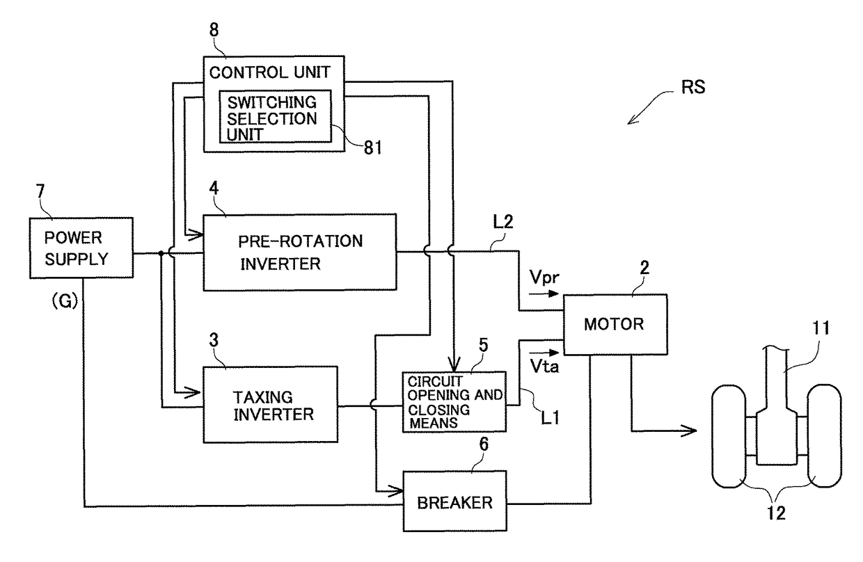
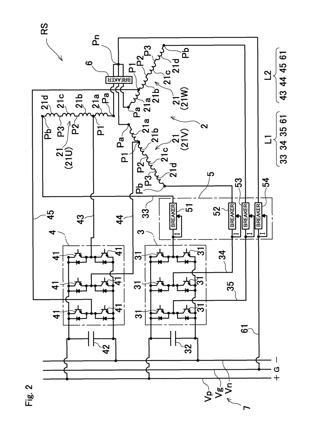
[0014]In such a configuration, the control unit supplies a voltage from the voltage supply unit, the motor is rotated, and the wheel is rotated by the motor. By changing a destination of the voltage supply of the voltage supply unit to one of the two voltage supply lines, it is possible to change the length of a winding to be energized. Thus, it is possible to obtain a low-speed high-torque output characteristic when driving by increasing the winding length, and obtain a high-speed low-torque output characteristic when driving by decreasing the winding length. Therefore, it is possible to perform taxiing of an aircraft at a low-speed high-torque, and perform pre-rotation of a wheel before landing at a high-speed low-torque by using a common motor. This suppresses an increase in manufacturing costs with a simple configuration, and achieves both taxiing and pre-rotation.
[0015]In order to reduce the size and weight of a motor by varying the length of a winding to be energized by using the same winding, it is preferable to provide a dividing point in the winding provided in the motor, and to configure two voltage supply lines of a first voltage supply line to be connected to one end and the other end of the winding, and a second voltage supply line to be connected to the one end and the dividing point.
[0018]In order to avoid an influence on a power supply line, prevent an occurrence of a failure and malfunction in other devices, and increase the safety, even if a fault occurs in a voltage supply unit, a circuit opening and closing unit, and a circuit or the like in a motor, it is preferable that the motor has multiple phases, the winding is provided for each phase, one end of each winding is connected to each other at a neutral point, and further connected to a power supply line through the neutral point, and a neutral point connecting and disconnecting unit, is further provided to enable an electrical connection and disconnection between the neutral point and one end of each winding.
[0019]According to the invention described above, it is possible to provide a wheel drive system for aircraft, which properly achieves both taxiing and pre-rotation by rotating a wheel using a common motor, and suppresses production costs with a simple configuration.

Problems solved by technology

Thus, consumption of fuel and wear of a brake by taxiing has been questioned.
However, a severe friction occurs between the wheel and the runway during touchdown, and the wheel surface is greatly worn.
A taxiing speed of an aircraft described above is relatively slow, approximately 35 km / h, and a large torque is required to move a heavy aircraft.
Thus, it is difficult to use a common motor to achieve both taxiing and pre-rotation.
Contrarily, when a wheel drive system is optimized to meet a required voltage of a motor for pre-rotation, characteristics of an electronic device provided in a voltage supply means exceed those for taxiing, and production costs may extremely increase.

Method used


Image

  • Wheel drive system for aircraft
  • Wheel drive system for aircraft
  • Wheel drive system for aircraft

Examples


Embodiment Construction

[0024]Hereinafter, embodiments of the present invention will be described with reference to the drawings.

[0025]A wheel drive system for aircraft RS according to an embodiment is configured as shown in FIG. 1. The wheel drive system for aircraft RS is configured to rotate and drive a wheel 12 that is supported by a support means 11 provided under an aircraft, and is comprised of a motor 2 that is directly or indirectly connected to the wheel 12, wherein the wheel 12 is rotated by the rotation of the motor 2. Although the wheel 12 is shown only two in this diagram, the wheel 12 may be provided in more number, and the power of the motor 2 may be distributed to rotate the wheels. Further, the diagram shows an example of wheel drive system for aircraft RS, in which wheels 12 are assumed to be provided in one support means 11, and the wheels 12 are rotated. Generally, an aircraft is provided with a plurality of such support means 11, and it is preferable to configure the wheel drive syste...


PUM


Abstract

Provided is a wheel drive system for aircraft RS including a motor 2 that is connected to a wheel 12, and provided with two voltage supply lines L1 and L2 for supplying the voltages Vta and Vpr with varying the length of a winding 21 to be energized; a voltage supply unit for supplying the voltage Vta and Vpr to the two voltage supply lines L1 and L2; and a control unit 8 for controlling the voltage supply unit, wherein the control unit 8 is configured to select one of the two voltage supply lines L1 and L2, and supply the voltage Vta or Vpr, by controlling the voltage supply unit.

Description

CROSS-REFERENCE TO RELATED APPLICATIONS[0001]This application claims priority of Japanese Patent Application No. 2014-075751 filed on Apr. 1, 2014. The contents of the applications are incorporated herein by reference in their entirety.BACKGROUND OF THE INVENTION[0002]1. Field of the Invention[0003]Embodiments of the present invention relate to a wheel drive system for aircraft for rotating a wheel of an aircraft.[0004]2. Description of the Related Art[0005]Conventionally, an aircraft utilizes the power of an engine for flight for movement in an airport (taxiing). Generally, a moving speed obtained by such power is greater than a moving speed for safe taxiing, and taxiing is done while braking by a brake. Thus, consumption of fuel and wear of a brake by taxiing has been questioned. For the purpose of suppressing these problems, a proposal such as Patent Literature JP-T-2013-514229 below has been made. The proposal includes a motor for rotating a wheel of an aircraft, enables taxiing...

Claims


Application Information

Patent Timeline
Patent Type & Authority Patents(United States)
IPC IPC(8): B64C25/40B64C25/34
CPCB64C25/405B64C25/40B64C25/34Y02T50/823Y02T50/80
Inventor SAITO, HIROSHINAKANISHI, NOBUYUKIOYORI, HITOSHITAKADA, MASAYUKI
Owner SINFONIA TECHNOLOGY CO LTD
Learn More