
Flexible pipe body layer and method of producing same

a flexible pipe and body layer technology, applied in the direction of flexible pipes, rigid pipes, applications, etc., can solve the problems of increasing the risk of production fluid cooling, pipe blockage, increasing the pressure associated with the environment, and increasing the depth

Active Publication Date: 2018-04-10
BAKER HUGHES ENERGY TECH UK LTD
View PDF18 Cites 0 Cited by
  • Summary
  • Abstract
  • Description
  • Claims
  • Application Information

AI Technical Summary

Benefits of technology

The sacrificial layer effectively mitigates strain and microcrazing issues, enhancing the durability and longevity of flexible pipes by allowing for controlled removal during manufacturing or testing, thus preventing premature failure and maintaining pressure containment.

Problems solved by technology

For example in such deep and ultra-deep water environments the cold ocean floor temperature increases the risk of production fluids cooling to a temperature that may lead to pipe blockage.
Increased depths also increase the pressure associated with the environment in which the flexible pipe must operate.
These irregularities are undesirable as they can act as areas of stress concentration.
This is particularly undesirable in the case of the inner fluid retaining layer, since this layer is a critical pressure containing layer of the flexible pipe body.
Such polymer layers may be subjected to quite severe non-uniform, highly localised strain deriving from the non-uniformity of the inner surface profile of the overlying armour layer.
The underlying polymer layer may thus tend to deform and creep into the gaps when under pressure.
This can in turn result in the formation of microcrazing or microcracking on the radially inner surface of the polymer layer.
This can increase the risk of failure of the polymer layer and may ultimately lead to loss of pressure containment, having an adverse effect on the lifetime of a flexible pipe.
However, the provision of one or more wear layers can have attendant disadvantages.
It is further known that occasionally in service the carcass layer and barrier layer of the flexible pipe body may internally collapse due to a pressure build up between the wear layer and the barrier layer, especially when the bore pressure (of the fluid being conveyed in the flexible pipe) is released.
This is an issue uniquely associated with flexible pipe body structures incorporating multi-layer extrusions.

Method used


Image

  • Flexible pipe body layer and method of producing same
  • Flexible pipe body layer and method of producing same
  • Flexible pipe body layer and method of producing same

Examples


Embodiment Construction

[0082]In the drawings like reference numerals refer to like parts.

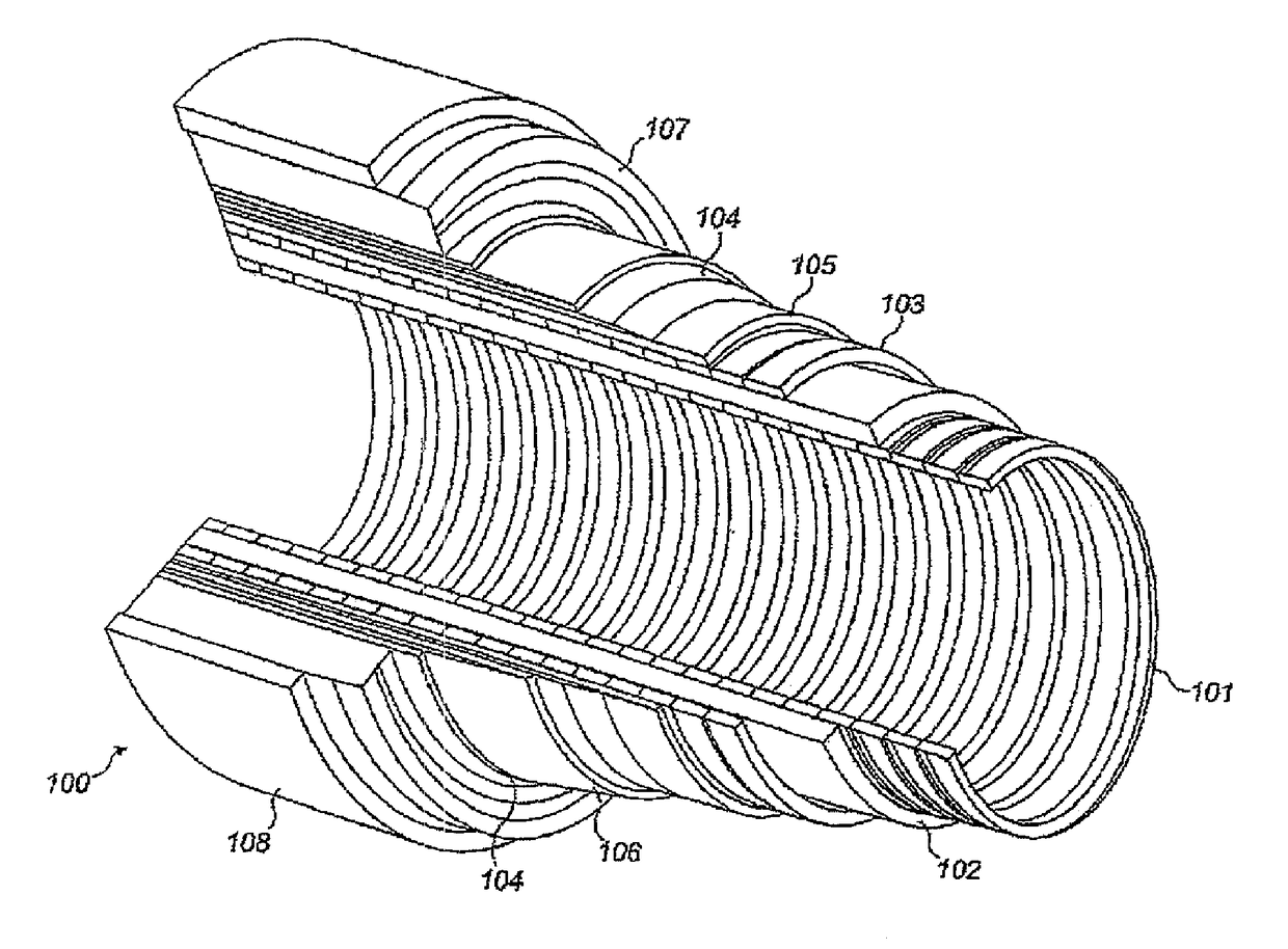
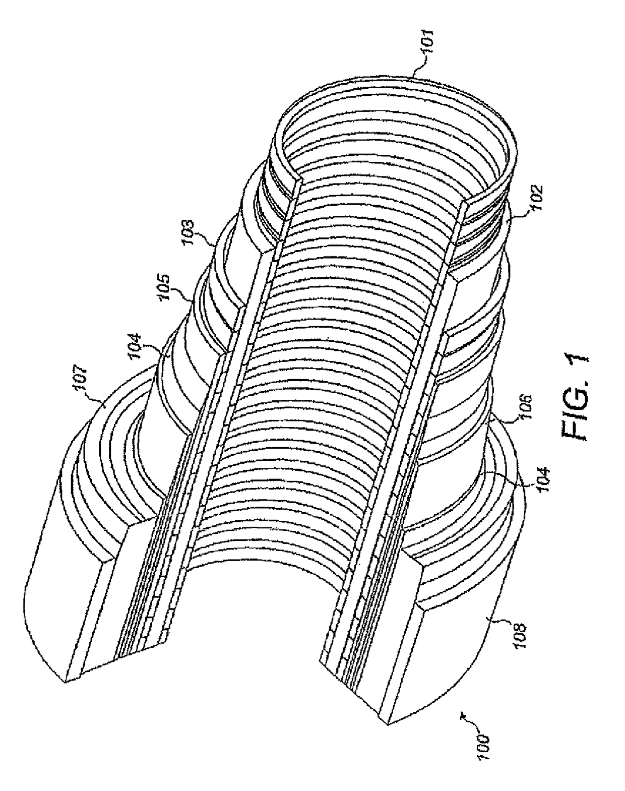
[0083]Throughout this specification, reference is made to a flexible pipe. It will be understood that a flexible pipe is an assembly of a portion of a pipe body and one or more end fittings in each of which a respective end of the pipe body is terminated. FIG. 1 illustrates how, in a typical arrangement, pipe body 100 may be formed from a combination of layered materials that form a pressure-containing conduit. In various embodiments, the pipe body of the present invention may usefully be of the general type illustrated in FIG. 1, it being noted nevertheless that although a number of particular layers are illustrated in FIG. 1, embodiments of the present invention are not confined to the illustrated arrangement. Rather, embodiments of the invention are broadly applicable to coaxial pipe body structures including two or more layers manufactured from a variety of possible materials. It is to be further noted that the la...


PUM

PropertyMeasurementUnit
internal diameteraaaaaaaaaa
depthaaaaaaaaaa
lay angleaaaaaaaaaa

Abstract

A flexible pipe body configured for offshore use or a flexible pipe precursor, and a method of preparing a flexible pipe are disclosed. The pipe body or precursor includes a sacrificial layer which is, at least partially, removable on contact with a solvent medium such as an aqueous solvent, in particular water.

Description

CROSS REFERENCE TO RELATED APPLICATIONS[0001]This is the U.S. National Stage of International Application No. PCT / GB2014 / 051395, filed May 7, 2014, which in turn claims the benefit of and priority to United Kingdom Patent Application No. GB1309887.6, filed Jun. 3, 2013.[0002]The present invention relates to a flexible pipe body or a flexible pipe body precursor and method of producing the same. In particular, but not exclusively, the present invention relates to the use of one or more materials which are at least partially soluble or at least partially dispersible in a solvent medium, in particular an aqueous medium, as one or more component layers of the flexible pipe body or the flexible pipe body precursor. The at least partially soluble or dispersible material forms, in embodiments, one or more sacrificial layers of the pipe body or pipe body precursor, the sacrificial layer or layers being removed (or removable) wholly or in part through contact with the solvent medium prior to...

Claims


Application Information

Patent Timeline
Patent Type & Authority Patents(United States)
IPC IPC(8): F16L11/16B32B1/08F16L11/12B32B9/02B32B9/04B32B15/02B32B23/08B32B27/08B32B15/08F16L11/08B32B27/28B32B27/36B32B27/34B32B27/32B32B27/30
CPCF16L11/08B32B9/02B32B9/045B32B15/02B32B15/08B32B23/08B32B27/08B32B27/286B32B27/30B32B27/322B32B27/34B32B27/36F16L11/083F16L11/12B32B1/08B32B2597/00B32B2307/554B32B2307/714F16L9/121F16L9/123
Inventor CLEMENTS, RICHARD ALASDAIR
Owner BAKER HUGHES ENERGY TECH UK LTD
Learn More