
Method and apparatus for current steering in high sensitivity, high linearity and large dynamic range high speed trans-impedance amplifiers

a transimpedance amplifier and high sensitivity technology, applied in the direction of amplifier combinations, amplifier modifications to reduce non-linear distortion, amplification control details, etc., can solve the problem that the core tia b>110/b> starts to degrade linearity for large input signals, the approach also suffers from significant disadvantages and drawbacks, and the dynamic range of control is limited. , to achieve the effect of high linearity, high sensitivity and high speed

Active Publication Date: 2018-04-03
INTEGRATED DEVICE TECH INC
View PDF3 Cites 0 Cited by
  • Summary
  • Abstract
  • Description
  • Claims
  • Application Information

AI Technical Summary

Benefits of technology

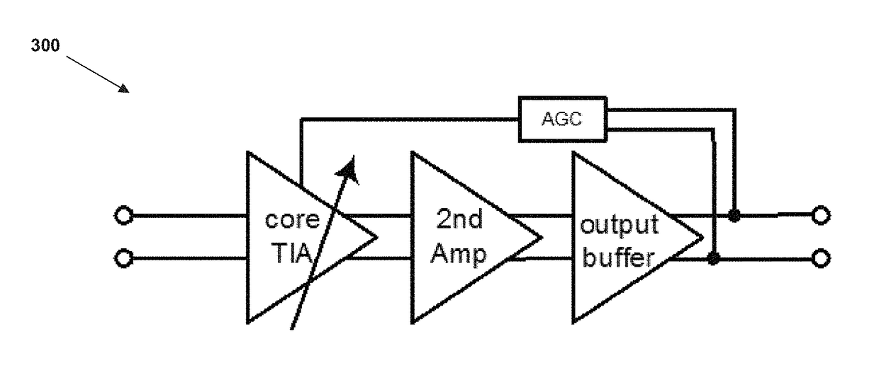
The present invention provides a linear, high sensitivity, high speed TIA that allows for a large dynamic range of input current, maintains high linearity and keeps constant output voltage, provides very high input sensitivity and large bandwidth, and allows input current monitoring without affecting input sensitivity. The TIA also provides a feedback path to maintain the same level of feedback even while the output signal is varied, which allows a wide and stable bandwidth, as well as a monitor to be placed in the TIA. The current steering gain control circuitry is performed at the very front end of the TIA, allowing for commensurate dynamic range improvement. The configuration of the core TIA with current steering gain control, feedback loop, and input monitoring has advantages such as reduced overall current, improved dynamic range, reduced THD, improved noise, and overall improved performance.

Problems solved by technology

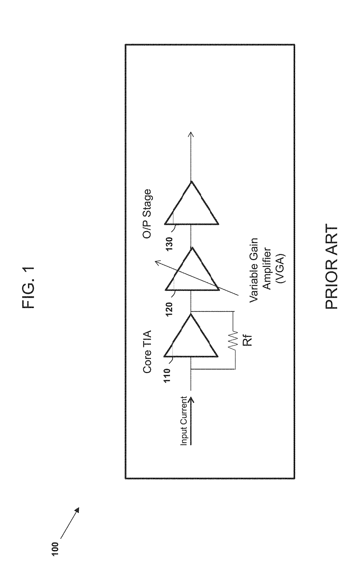
With respect to this design, the disadvantage is that the core TIA 110 starts to degrade linearity for large input signals.
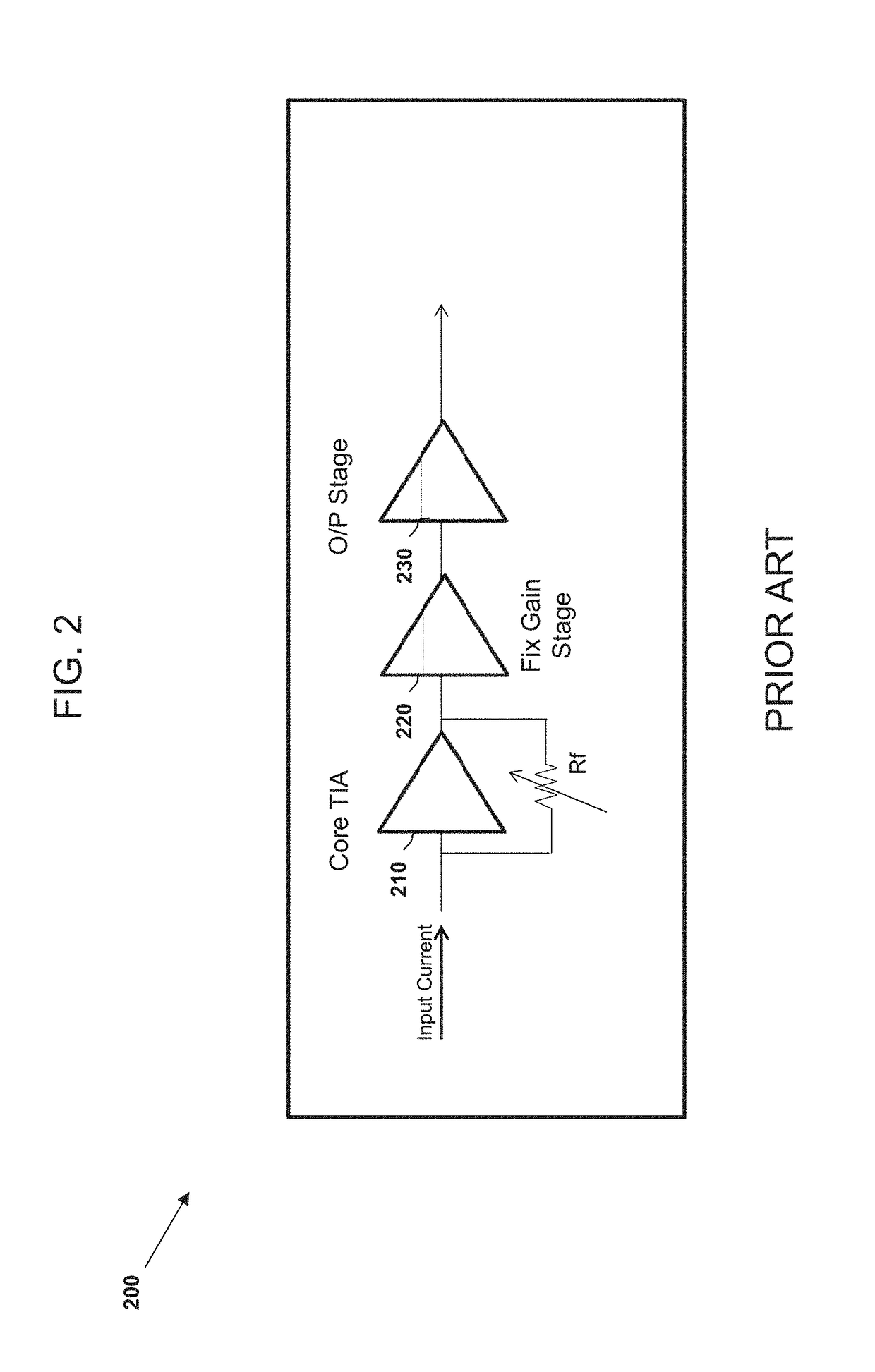
However, similar to the TIA design of FIG. 1, this approach also suffers from significant disadvantages and drawbacks.
In particular, the dynamic range of control is limited, and the frequency response changes with the variation of Rf (Gain).

Method used


Image

  • Method and apparatus for current steering in high sensitivity, high linearity and large dynamic range high speed trans-impedance amplifiers
  • Method and apparatus for current steering in high sensitivity, high linearity and large dynamic range high speed trans-impedance amplifiers
  • Method and apparatus for current steering in high sensitivity, high linearity and large dynamic range high speed trans-impedance amplifiers

Examples


Embodiment Construction

[0028]In accordance with the need in the art, the invention is directed to a linear, high sensitivity, high speed TIA which allows a large dynamic range of input current up to very large values, while maintaining high linearity and keeping constant output voltage, e.g., Automatic Gain Control (AGC) Mode. The TIA further tends to maintain the same frequency response across the full gain control range in AGC mode, while providing very high input sensitivity and large bandwidth, and allowing input current monitoring without affecting input sensitivity. In other words, the novel circuit disclosed herein provides for the feedback path to maintain the same level of feedback even while the output signal is varied. This allows a wide and stable bandwidth, as well as a monitor to be placed in the TIA.

[0029]The aforementioned features are achieved by at least the novel TIA design, as shown by the all the figures in the present disclosure. For example, FIG. 3A illustrates a circuit diagram of ...


PUM


Abstract

The present invention relates to a linear, high sensitivity, high speed trans-impedance amplifier (TIA) which allows a large dynamic range of input current up to very large values, maintains high linearity and keeps constant output voltage, maintains the same frequency response across the full gain control range, provides very high input sensitivity and large bandwidth, and allows input current monitoring without affecting input sensitivity. In other words, the novel circuit disclosed herein provides for the feedback path to maintain the same level of feedback even while the output signal is varied. This allows a wide and stable bandwidth, as well as a monitor to be placed in the TIA.

Description

CROSS REFERENCE TO RELATED APPLICATIONS[0001]This application claims the benefit of U.S. Provisional Application No. 62 / 083,058, filed Nov. 21, 2014, the contents of which are incorporated herein by reference in its entirety.FIELD OF INVENTION[0002]The field of invention is a current steering in high sensitivity, high linearity and large dynamic range high speed trans-impedance amplifiers.BACKGROUND[0003]In electronics, a trans-impedance amplifier (TR) is essentially a current-to-voltage converter. The TIA may be configured to amplify an input current from an electrical component, such as a sensor or photodiode, to a usable voltage in a particular circuit. TIAs are typically implemented using operational amplifiers.[0004]FIG. 1 illustrates a prior art TIA 100, having a core TIA 110, a linear variable gain amplifier (VGA) 120 and an output stage 130. For such a typical, high linear TIA 100, the automatic gain control is achieved by means of the linear VGA 120, situated between the fi...

Claims


Application Information

Patent Timeline
Patent Type & Authority Patents(United States)
IPC IPC(8): H03F3/08H03F1/08H03G1/00H03F3/45H03F3/68H03F1/34H03F1/32
CPCH03F3/082H03F1/086H03F1/3205H03F1/342H03F3/45475H03F3/68H03G1/0035H03G1/0023H03F2203/45652H03F2200/153H03F2200/408H03F2200/462H03F2203/45138
Inventor SHAW, MICHAEL
Owner INTEGRATED DEVICE TECH INC
Learn More