
Calibration of a device for measuring an electric field in a conducting medium

a technology of conducting medium and measuring device, which is applied in the direction of measuring device, electrostatic field measurement, instruments, etc., can solve the problems of general bulky voltage measurement electrometer, metalrology problems,

Active Publication Date: 2018-04-03
COMMISSARIAT A LENERGIE ATOMIQUE ET AUX ENERGIES ALTERNATIVES
View PDF9 Cites 0 Cited by
  • Summary
  • Abstract
  • Description
  • Claims
  • Application Information

AI Technical Summary

Problems solved by technology

A disadvantage of voltage measurement electrometers is that only a very small portion of the current propagating in the conducting medium formed by the sea water is deviated in the voltage measurement device, which raises metrology problems.
Further, voltage measurement electrometers are generally bulky.

Method used


Image

  • Calibration of a device for measuring an electric field in a conducting medium
  • Calibration of a device for measuring an electric field in a conducting medium
  • Calibration of a device for measuring an electric field in a conducting medium

Examples


Embodiment Construction

[0031]For clarity, the same elements have been designated with the same reference numerals in the various drawings and, further, the various drawings are not to scale. Further, in the following description, unless otherwise indicated, terms “approximately”, “substantially”, “about”, and “in the order of” mean “to within 10%”.

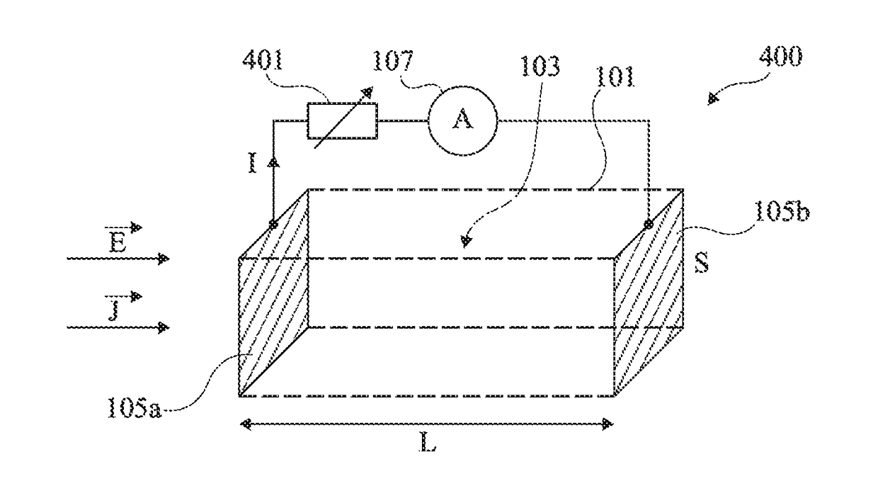
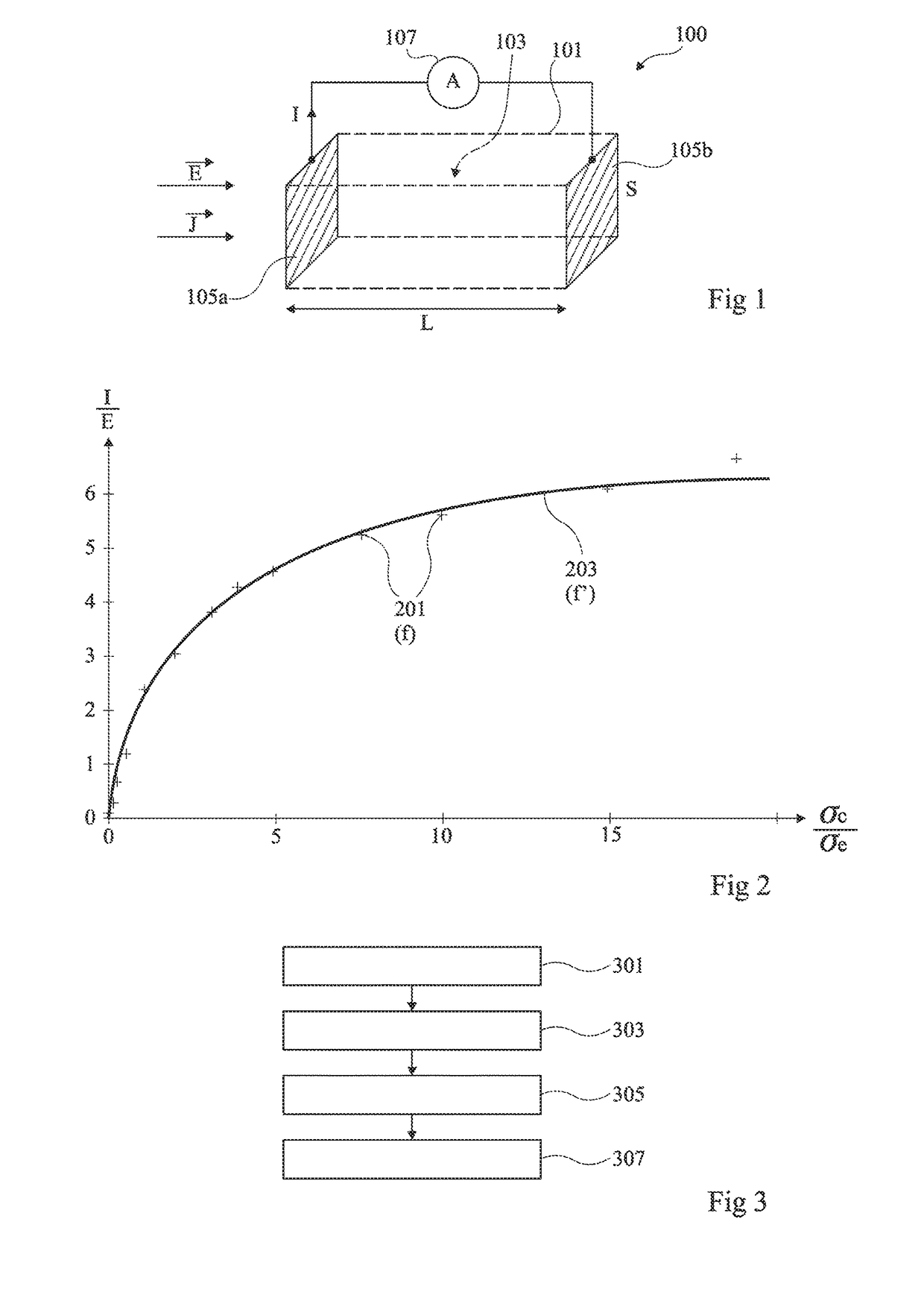
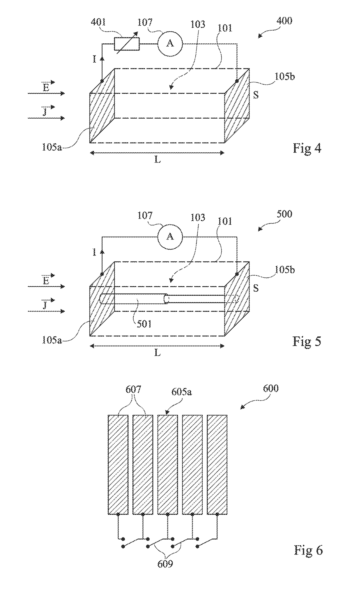
[0032]FIG. 1 schematically illustrates an example of a current measurement electrometer 100 intended to be placed in a conducting medium where an electric field is desired to be measured, for example, sea water. Device 100 comprises a tightly closed enclosure 101, shown in dotted lines in the drawing, delimiting a volume 103 of an insulating medium, for example, air or vacuum. Two electrodes 105a and 105b are arranged outside of enclosure 101, so that each electrode has a surface in contact with the conducting medium when the electrometer is immersed. In this example, the two electrodes 105a and 105b are approximately planar and parallel to each other, have subs...


PUM


Abstract

A device for measuring an electric field in a conducting medium comprises: two electrodes separated by a volume of an insulating medium; a device for measuring current coupled to said electrodes; and adjustment elements making it possible to vary a quantity on which the electrical conductivity of the field measuring device depends.

Description

[0001]The present patent application claims the priority benefit of French patent application 13 / 60900, which is herein incorporated by reference.BACKGROUND[0002]The present disclosure relates to a method and a device for measuring an electric field in a conducting medium. It particularly applies to submarine electric field measurements.DISCUSSION OF THE RELATED ART[0003]An offshore electric field measurement device, or ocean electrometer, comprising two immersed electrodes separated by a distance l, connected to a voltage measurement device, has already been provided. To measure an electric field E in the area located between the two electrodes, voltage U between the electrodes is measured. Field E can be deduced from this measurement by formula E=U / l. Electrometers of this type are called “voltage measurement” electrometers.[0004]A disadvantage of voltage measurement electrometers is that only a very small portion of the current propagating in the conducting medium formed by the s...

Claims


Application Information

Patent Timeline
Patent Type & Authority Patents(United States)
IPC IPC(8): G01R29/12G01R5/28G01R29/08G01R35/00G01R31/26
CPCG01R29/12G01R5/28G01R29/0814G01R35/00G01R35/005G01R29/0842G01R31/2642
Inventor BAICRY, MATHIEULE PRADO, MATTHIEULEFROU, CHRISTINEROUVE, LAURE-LINE
Owner COMMISSARIAT A LENERGIE ATOMIQUE ET AUX ENERGIES ALTERNATIVES
Learn More