Control system for clutch

a control system and clutch technology, applied in the direction of clutches, fluid actuated clutches, non-mechanical actuated clutches, etc., can solve the problems of reducing the controllability of the clutch disc, and reducing the frequency at which the first engaging element is driven. , to achieve the effect of less likely or unlikely to be cumbersome and complicated

Active Publication Date: 2018-04-03
TOYOTA JIDOSHA KK
View PDF12 Cites 0 Cited by
  • Summary
  • Abstract
  • Description
  • Claims
  • Application Information

AI Technical Summary

Benefits of technology

[0008]The invention provides a control system for a clutch, which can curb reduction of the control response, and can also curb unintended transmission of torque via engaging elements.
[0010]According to the invention, the clutch is configured to transmit torque when the first engagement element moves in the axial direction until it contacts with the second engaging element. The first engaging element or the second engaging element inevitably undergoes plane deflection depending on the rotational speed. Therefore, the control system is configured to learn the engagement start position of the first engaging element, according to the rotational speed of one of the engaging elements, so as to curb unintended contact between the first engaging element and the second engaging element even when the first engaging element or the second engaging element undergoes plane deflection. Accordingly, the position of the first engaging element at the time when the first engaging element and the second engaging element start contacting with each other can be learned in view of the amount of plane deflection of the first engaging element or the second engaging element. As a result, while the first engaging element and the second engaging element are spaced apart from each other, the first engaging element and the second engaging element can be moved to be close to each other, within the range in which the first engaging element and the second engaging element do not unintendedly contact with each other. Therefore, the control response at the time when the first engaging element is brought into contact with the second engaging element can be improved, and unintended transmission of torque can be curbed or prevented.
[0012]The control system leans the engagement start position again, after a lapse of the predetermined period from the time when the engagement start position was learned. In this manner, when the amount of plan deflection of the first engaging element or the second engaging element varies due to chronological changes thereof, or when contact surfaces of the engaging elements are worn, for example, otherwise possible reduction of the control response due to the chronological changes and unintended transmission of torque can be curbed or prevented.
[0014]Further, if the rotational speed of one of the engaging elements is divided into two or more ranges delimited by predetermined rotational speeds, and the engagement start position of the first engaging element is learned for each of the ranges, the learning control is less likely or unlikely to be cumbersome and complicated, and the frequency at which the first engaging element is driven can be reduced.

Problems solved by technology

Accordingly, friction surfaces of the clutch disc and the pressure plate or the flywheel become inevitably worn.
If the friction surfaces are worn, the position of the pressure plate when it starts being engaged with the clutch disc changes, or the position of the pressure plate in the fully engaged state changes, which may result in reduction of the clutch controllability.
On the other hand, the balance of the mass of the clutch disc is not uniform in the circumferential direction, or the radial direction, or the axial direction, and, as a result, the clutch disc may undergo plane deflection while it is rotating.
Therefore, if the clearance between the pressure plate and the clutch disc in the fully released state is reduced so as to curb reduction of the control response as described above, unintended transmission of torque may take place, due to plane deflection of the clutch disc.

Method used


Image

  • Control system for clutch
  • Control system for clutch
  • Control system for clutch

Examples


Embodiment Construction

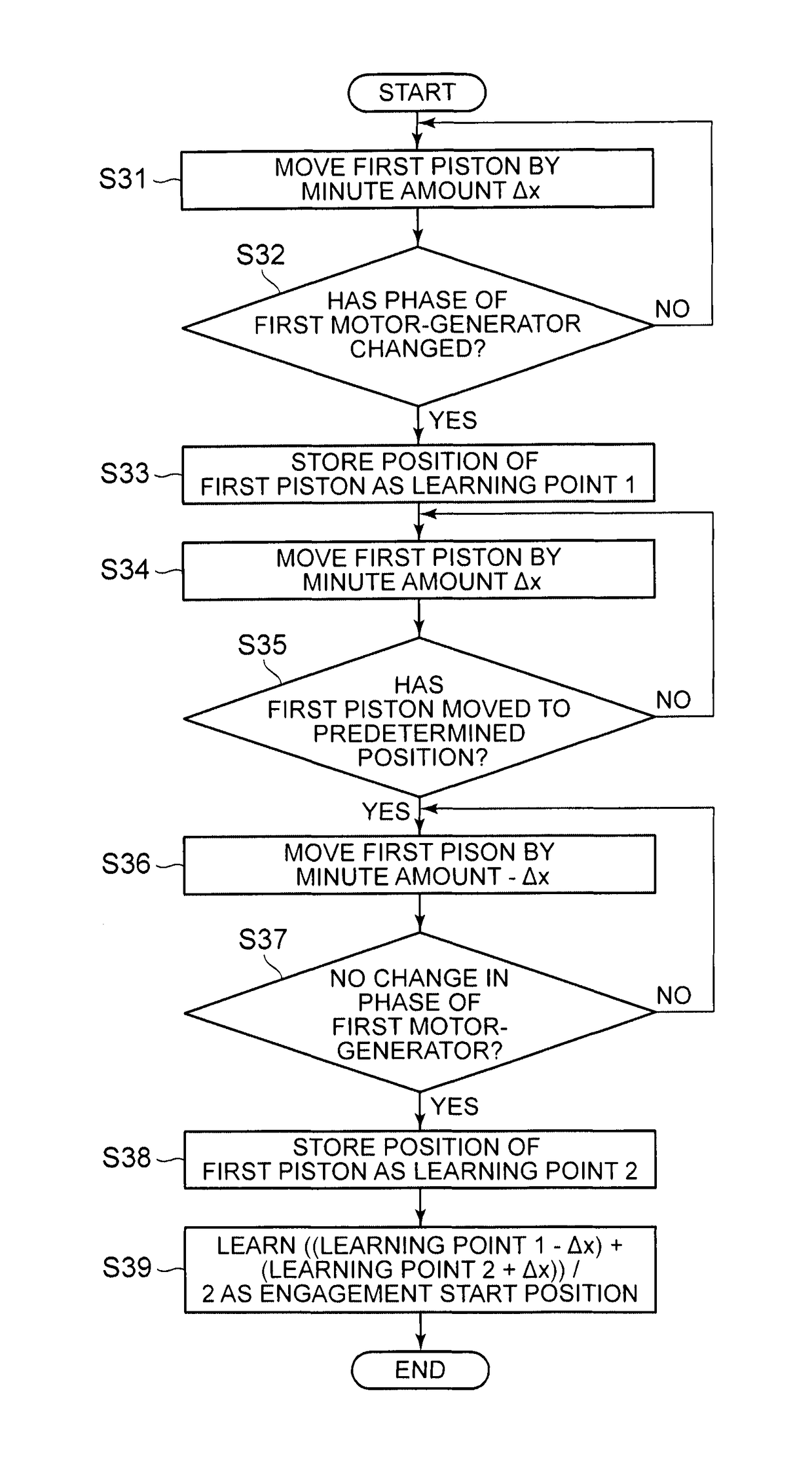
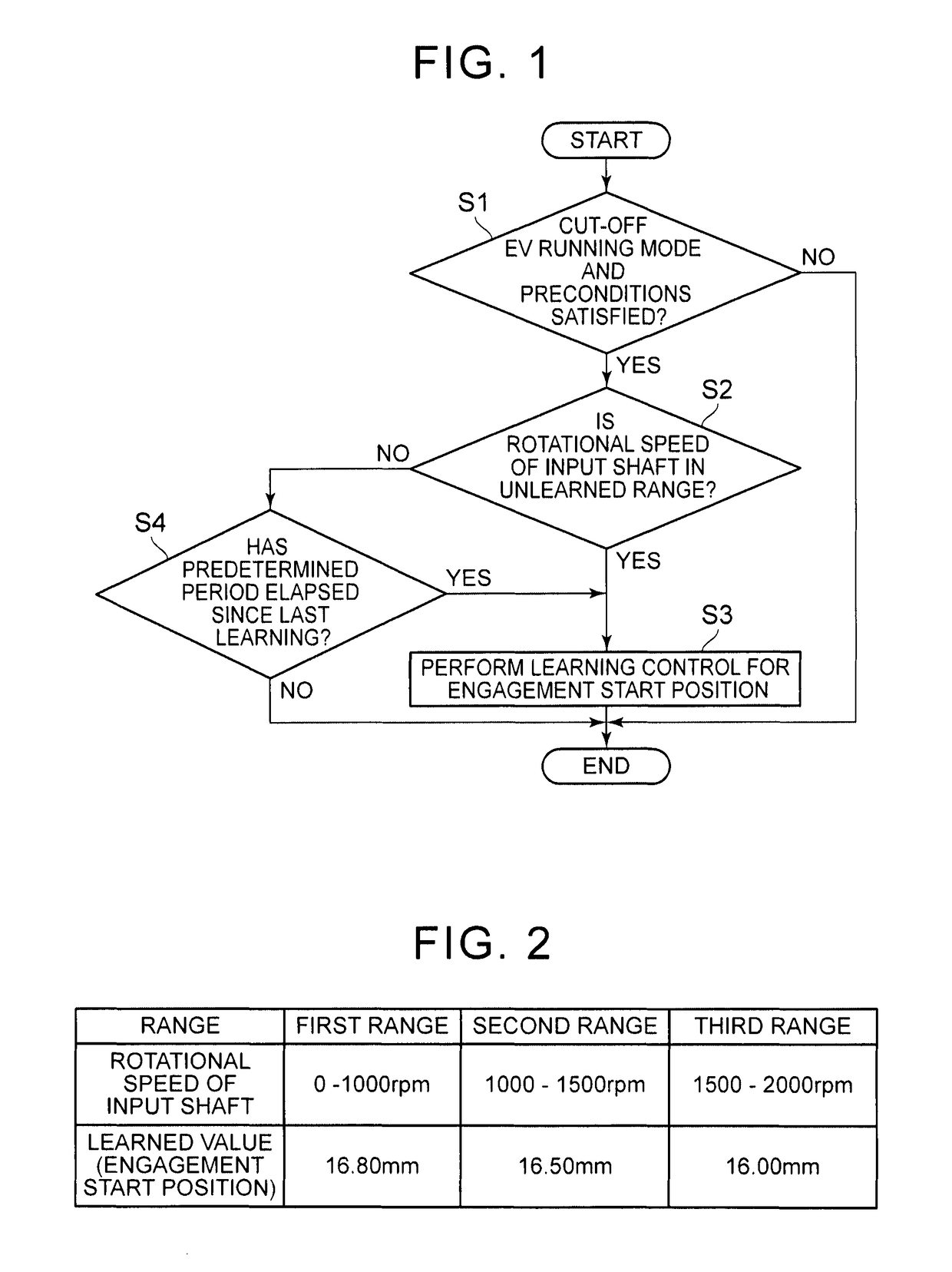
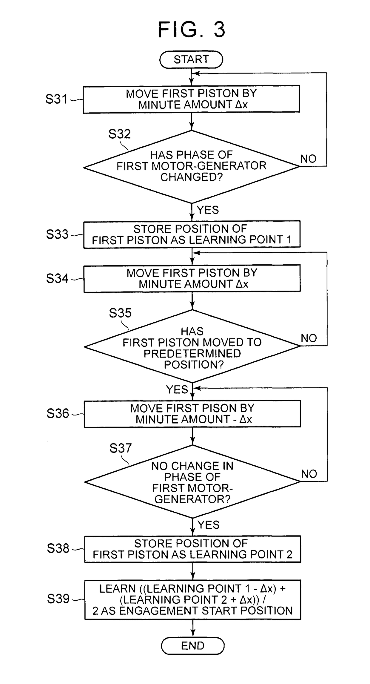
[0024]The clutch according to the invention includes the first engaging element that is movable in an axial direction, and a second engaging element that is opposed to the first engaging element in the axial direction and is located so as to be rotatable relative to the first engaging element. When the first engaging element is brought into contact with the second engaging element, the first and second engaging elements are coupled to each other such that torque can be transmitted between these elements. One example of vehicle including the clutch thus configured is schematically shown in FIG. 5. The vehicle shown in FIG. 5 is a hybrid vehicle including an engine 1 and two motor-generators 2, 3 as driving power sources, and a power split device 5 is coupled to an output shaft 4 of the engine 1 via a clutch K0. The power split device 5 is configured similarly to a known power split device used in a two-motor-type hybrid vehicle, and is formed by a single-pinion-type planetary gear tr...


PUM


Abstract

A control system is for a clutch mechanism. The clutch mechanism includes a first engaging element, a second engaging element, and a piston. The first engaging element is configured to be moved according to change of a position of the piston. The first engaging element and the second engaging element are coupled to each other such that torque can be transmitted from the first engaging element to the second engaging element. The control system comprises an electronic control unit. The electronic control unit is configured to learn an engagement start position, according to a rotational speed of one of the first engaging element and the second engaging element. The engagement start position is a position of the first engaging element at the time when the first engaging element and the second engaging element start contacting with each other.

Description

CROSS-REFERENCE TO RELATED APPLICATIONS[0001]This is a national phase application based on the PCT International Patent Application No. PCT / IB2015 / 000676 filed May 12, 2015, claiming priority to Japanese Patent Application No. 2014-100094 filed May 14, 2014, the entire contents of both of which are incorporated herein by reference.BACKGROUND OF THE INVENTION[0002]1. Field of the Invention[0003]The invention relates to a control system for a clutch, which is configured to bring mutually opposed engaging elements into contact with each other, so as to couple the engaging elements with each other such that torque can be transmitted therebetween.[0004]2. Description of Related Art[0005]A hybrid vehicle having an engine and a motor as driving power sources is described in Japanese Patent Application Publication No. 2010-143365 (JP 2010-143365 A). When the hybrid vehicle runs in an EV running mode, using only power of the motor as driving force, the engine is cut off from a power transmis...

Claims


Application Information

Patent Timeline
Patent Type & Authority Patents(United States)
IPC IPC(8): F16D48/06F16D25/06
CPCF16D48/06F16D2500/70605F16D2500/1026F16D2500/1045F16D2500/10412F16D2500/3026F16D2500/3067F16D2500/30415F16D2500/30426F16D2500/3166F16D2500/5012F16D2500/50239F16D2500/50245F16D2500/50251F16D2500/7041F16D25/06
Inventor OSHIUMI, YASUHIRO
Owner TOYOTA JIDOSHA KK
Why Eureka
Try Eureka