
Coherent diffractive imaging with spaced-apart beams

a beam and beam technology, applied in the field of coherent diffractive imaging, can solve the problems of spatial non-distinct beams of illuminating radiation and more advanced cdi techniques

Active Publication Date: 2018-03-06
KM LABS INC
View PDF1 Cites 0 Cited by
  • Summary
  • Abstract
  • Description
  • Claims
  • Application Information

AI Technical Summary

Benefits of technology

[0009]In the present invention, spatially distinct beams encounter different areas of the sample providing a scan area that is larger by the number of beams used and aiding the pre-existing reconstruction algorithms.

Problems solved by technology

More advanced CDI techniques are limited to spatially non-distinct beams.
The traditional limitation that the illuminating radiation be spatially non-distinct produces a few disadvantages: 1) The total scanned area in the case of spatially non-distinct beams is smaller than in our technique 2) Spatially non-distinct beams necessarily encounter the same object during a scan hindering image reconstruction.

Method used


Image

  • Coherent diffractive imaging with spaced-apart beams
  • Coherent diffractive imaging with spaced-apart beams
  • Coherent diffractive imaging with spaced-apart beams

Examples


Embodiment Construction

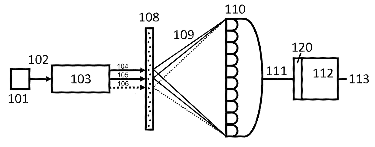
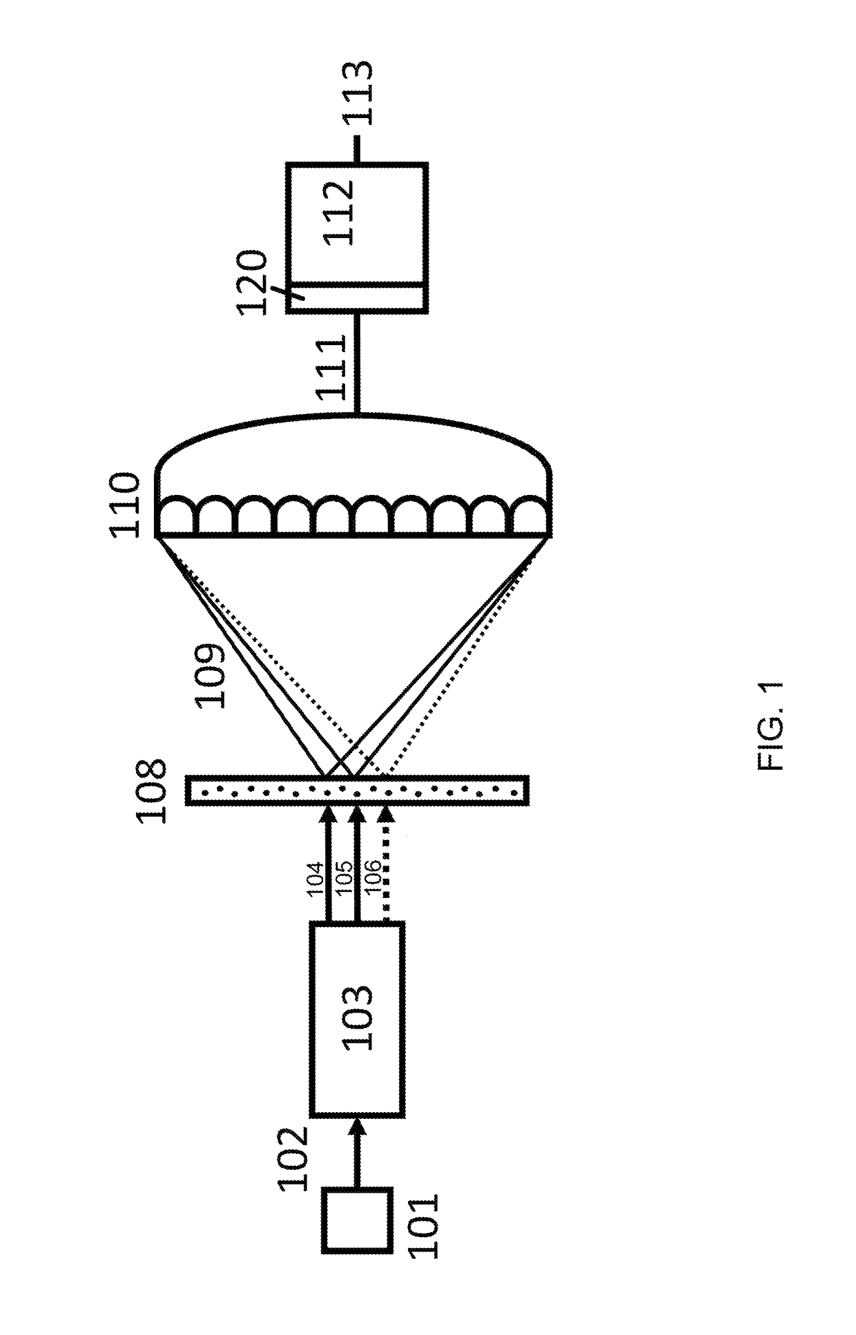
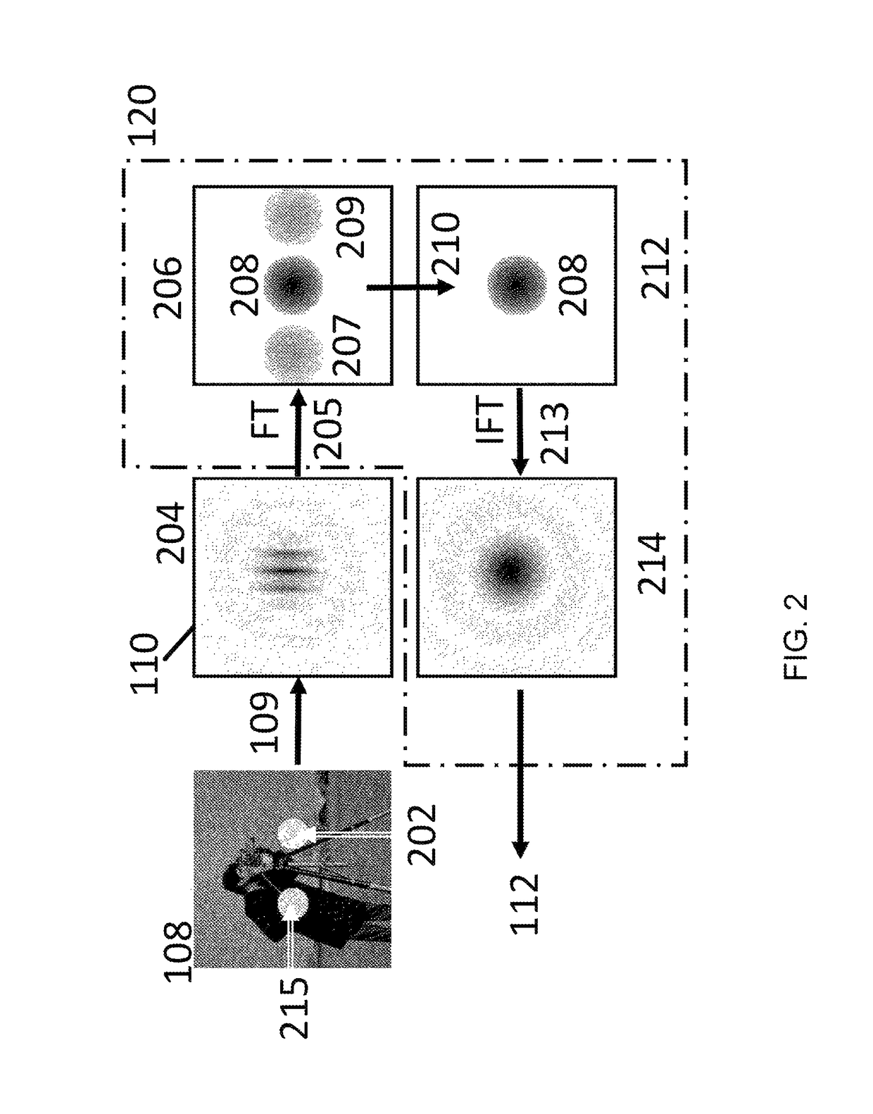
[0023]FIG. 1 is a schematic block diagram that depicts coherent diffractive imaging (CDI) using multiple spatially distinct beams. An at least partially coherent source 101 creates a single beam 102 that enters a system 103 to convert it into multiple beams 104,105,106. Those skilled in the art will know that this can be done with a pair of diffraction gratings to spatially separate different wavelength radiation, with a birefringent crystal to separate different polarization radiation, with a pinhole array to generate spatially separate beams of similar properties, etc. Alternatively, an at least partially coherent source generates multiple beams: for example, random lasers. These beams 104-106 are incident on a sample 108. The diffracted waves 109 are measured simultaneously on a pixel detector 110. Simultaneous herein means detected simultaneously (within the acquisition time of the detector). Pixel herein means the smallest area on the detector in which we can make a distinct me...


PUM


Abstract

Apparatus and methods for Coherent Diffractive Imaging with multiple, simultaneous, spatially distinct beams chosen and configured to isolate incoherent sums of beam diffraction such that interference between the multiple beams is not present in the data prior to computationally reconstructing the image. This is accomplished through selecting the multiple beams to be non-interfering modes, or through designing the apparatus such that the interference is not recorded, or through processing the collected data to filter the interference before reconstructing the image.

Description

[0001]This invention was made with government support under contract number DARPA-12-63-PULSE-FP-004. The government has certain rights in this invention.BACKGROUND OF THE INVENTION[0002]Field of the Invention[0003]The present invention relates to Coherent Diffractive Imaging with multiple, simultaneous, spatially distinct beams.[0004]Discussion of Related Art[0005]Coherent diffractive imaging (CDI), for example ptychography, is an emerging technique that enables wavelength- and diffraction-limited imaging without the need for refractive or reflective image forming optics. An object is illuminated and the resulting diffraction pattern is measured with a pixel detector. Then an image of the object is computationally reconstructed from the measured data using well known techniques such as those discussed in D. J. Batey, D. Claus, and J. M. Rodenburg, “Information multiplexing in ptychography,”Ultramicroscopy, vol. 138 C, pp. 13-21, December 2013 and P. Thibault and A. Menzel, “Reconst...

Claims


Application Information

Patent Timeline
Patent Type & Authority Patents(United States)
IPC IPC(8): G06T11/00G02B27/58G02B27/42
CPCG06T11/005G02B27/58G02B27/4205G02B21/0056G03H1/0866G03H2222/20G03H1/0443G03H1/0465
Inventor KARL, ROBERT M.ADAMS, DANIEL E.BEVIS, CHARLES S.KAPTEYN, HENRY C.MURNANE, MARGARET M.
Owner KM LABS INC
Learn More