
Method for operating a clutch transmission, clutch transmission

a clutch transmission and clutch technology, applied in mechanical equipment, vehicle sub-unit features, transportation and packaging, etc., can solve the problem of high current consumption of electric motors needed to operate the pump against the backpressure, and achieve the effect of quick and easy determination during operation

Active Publication Date: 2018-02-27
AUDI AG
View PDF16 Cites 3 Cited by
  • Summary
  • Abstract
  • Description
  • Claims
  • Application Information

AI Technical Summary

Benefits of technology

The invention provides a simple and affordable way to ensure a high pressure in a hydraulic system for a clutch transmission. The method involves measuring current consumption to determine which hydraulic circuit is currently being supplied, and if there is a charge requirement. This takes into account the temperature of the hydraulic medium and ensures accurate measurement of current consumption. This technology ensures efficient and reliable operation of the clutch transmission.

Problems solved by technology

This exploits the fact that the backpressure in the hydraulic circuit operating on the pump is reflected in the current consumption of the electric motor.
The higher the pressure in the hydraulic circuit is, the higher is the current consumption of the electric motor necessary to operate the pump against the backpressure.

Method used


Image

  • Method for operating a clutch transmission, clutch transmission
  • Method for operating a clutch transmission, clutch transmission

Examples


Embodiment Construction

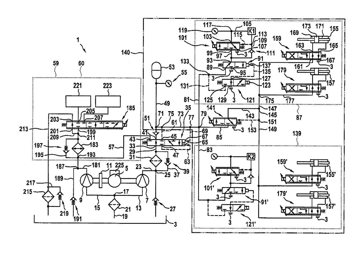
[0026]The hydraulic circuit of the invention will now be described in detail with reference to FIG. 1.

[0027]FIG. 1 shows a hydraulic circuit 1 which is used to actuate, and in particular to couple and engage and disengage gears of a dual clutch transmission and to cool the transmission. The hydraulic circuit 1 includes a tank 3, serving in particular as a reservoir or sump for a hydraulic medium used for operation and cooling, in which the hydraulic medium is preferably stored unpressurized. An electric motor 5 driving a first pump 7 and a second pump 9 is provided. Preferably, the speed and direction of rotation of the electric motor 5 can be controlled, preferably regulated. The first pump 7 is fixedly connected to the electric motor 5, i.e. without a separating element. In other words, the pump 7 is always driven when the electric motor 5 is running and the hydraulic medium is preferably conveyed in the same direction in the both directions of rotation. The pump 9 is preferably c...


PUM


Abstract

According to a method for operating a clutch transmission, especially a dual clutch transmission, which includes a hydraulic circuit having at least one pump for delivering hydraulic medium and at least one pressure accumulator for accommodating and making available a hydraulic medium under pressure, the pump associated with an electric motor is operated depending on a charge requirement of the pressure accumulator. To determine the charge requirement, the pump is driven by the electric motor, and the current consumed by the electric motor in the process is detected to determine the charge requirement.

Description

CROSS-REFERENCES TO RELATED APPLICATIONS[0001]This application is the U.S. National Stage of International Application No. PCT / EP2012 / 001847, filed Apr. 30, 2012, which designated the United States and has been published as International Publication No. WO 2012 / 152393 and which claims the priority of German Patent Application, Serial No. 10 2011 100 802.4, filed May 6, 2011, pursuant to 35 U.S.C. 119(a)-(d).BACKGROUND OF THE INVENTION[0002]The invention relates to a hydraulic circuit for controlling and cooling a clutch transmission, in particular a dual clutch transmission, in particular of a motor vehicle, with two clutch cylinders and a plurality of preferably double-sided actuatable switching cylinders.[0003]Dual clutch transmissions are preferably used in passenger cars. A dual clutch transmission generally includes two coaxially disposed transmission input shafts, which are each associated with a sub-transmission. A clutch is associated with each of the transmission input shaf...

Claims


Application Information

Patent Timeline
IPC IPC(8): F16D25/00F16D28/00F16H61/00F16H61/30F16H61/688F16D121/24
CPCF16D28/00F16H61/0031B60Y2400/3084F16H2061/305F16H61/688F16H2061/0034F16D2121/24
Inventor SCHULLER, DIETMARAMMLER, STEFANFLEISCHMANN, HANS-PETER
Owner AUDI AG
Learn More