
Waterfall thread for inserts

a waterfall thread and insert technology, applied in the direction of threaded fasteners, fastening means, mechanical equipment, etc., can solve the problems of high processing cost, difficult to achieve significant holding strength against pullout with push-in inserts, and high cost of outer surfaces of inserts, so as to achieve efficient and fast manufacturing and reduce the cost

Active Publication Date: 2018-02-27
ILLINOIS TOOL WORKS INC
View PDF19 Cites 4 Cited by
  • Summary
  • Abstract
  • Description
  • Claims
  • Application Information

AI Technical Summary

Benefits of technology

The waterfall thread is a new type of continuous, curved thread that can be made quickly and easily using standard rolling processes and materials. It has both axial and circumferential portions, and is designed to weave back and forth along a straight-line path. The technical effect is improved efficiency and speed in manufacturing a high-quality, waterfall-shaped thread.

Problems solved by technology

Ultrasonic insertion can be performed relatively quickly, but the process tends to be expensive.
Mechanical insertion such as this can be performed quickly, but the machining process required to form the outer surface of the insert adds significantly to overall cost.
Further, mechanical insertions tend to channel or direct the material of the anchor component, and it has been difficult to achieve significant holding strength against pullout with push-in inserts.
Further, to facilitate easy and rapid machining of inserts, it has been known to use expensive materials, such as brass.
Knurls, undercuts and other such formations can be formed readily in brass; however, the costs of parts made of such materials are high.

Method used


Image

  • Waterfall thread for inserts
  • Waterfall thread for inserts
  • Waterfall thread for inserts

Examples


Embodiment Construction

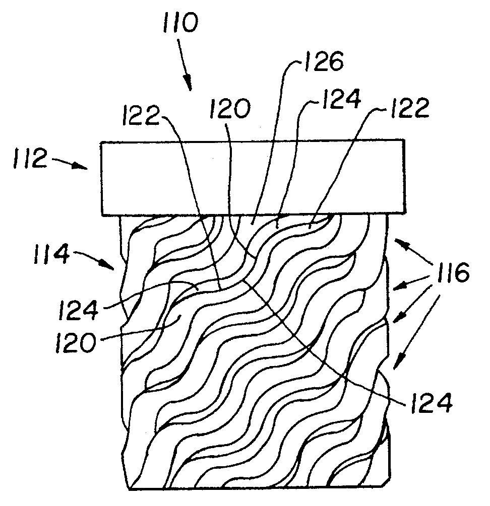
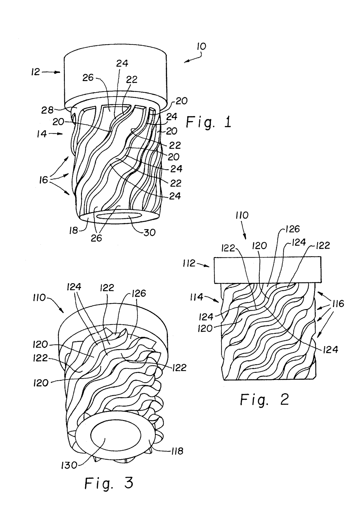
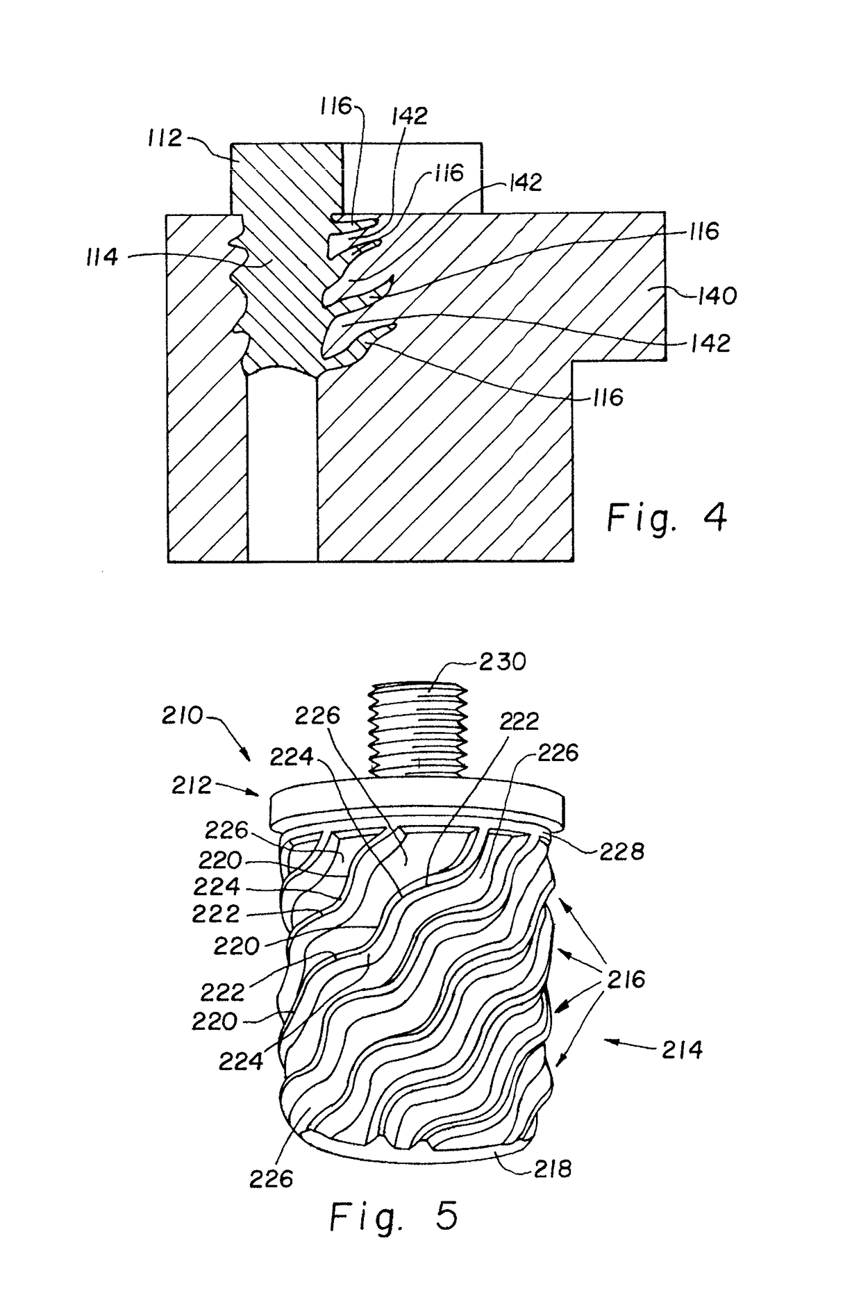
[0017]With reference now more particularly to the drawings and to FIG. 1 in particular, a female threaded insert 10 having a waterfall thread pattern on the exterior thereof is shown. Insert 10 is a monolithic body and includes a head 12 and a shank 14. A plurality of individual threads 16 are provided on shank 14. Each thread is a protrusion or ridge projecting from the outer surface of shank 14. Each thread is continuous from one end to the other and includes pluralities of portions differently angled with respect to the axial and circumferential directions of shank 14. Accordingly, each thread 16 includes substantially more axially oriented portions 20 and substantially more circumferentially oriented portions 22, with continuous transitions 24 interconnecting sequential portions of a thread 16 that are more axially oriented and more circumferentially oriented portions. Individual threads 16 are spaced from each other to define inter-thread channels 26, with each thread 16 extend...


PUM


Abstract

An external surface for a fastener insert to be embedded in a component includes waterfall threads extending along an outer surface of the portion to be embedded. The waterfall thread includes a first portion and a second portion, the first portion being more axially oriented on the surface than the second portion, and the second portion being more circumferentially oriented on the surface than the first portion. Continuous transitions are provided between adjacent first and second portions in a thread.

Description

CROSS-REFERENCE TO RELATED APPLICATIONS[0001]The present application is based on International Application No. PCT / US2011 / 026212, filed Feb. 25, 2011 and claims the benefits of U.S. Provisional Application Ser. No. 61 / 309,168 filed Mar. 1, 2010.FIELD OF THE INVENTION[0002]The present invention relates generally to fasteners and fastener systems, and, more particularly, to fastener components of fastener systems that are embedded in another part, often of dissimilar material.BACKGROUND OF THE INVENTION[0003]It is known to provide fastening systems that include threaded inserts to be embedded in plastic or other components to receive a screw or bolt for holding a second component in an assembly. For example, plastic parts in automobiles, computers, appliances of different types, and various other assemblies are known to be provided with metal inserts having internal threads so that another part can be held thereto by a bolt or screw engaged with the threaded insert. It is also known t...

Claims


Application Information

Patent Timeline
Patent Type & Authority Patents(United States)
IPC IPC(8): F16B37/12
CPCF16B37/122F16B37/127
Inventor PRABHU, SANDEEP
Owner ILLINOIS TOOL WORKS INC
Learn More