
Method and apparatus for producing large uniform thickness nanomaterial sheets

Active Publication Date: 2018-02-27
INNOVATECH ENG
View PDF2 Cites 1 Cited by
  • Summary
  • Abstract
  • Description
  • Claims
  • Application Information

AI Technical Summary

Benefits of technology

The patent describes a device that can deposit nanoparticles onto a filter membrane using compressed air. The device has a controlled pressure and volume of the suspension, which prevents damage to the membrane and ensures uniform deposition of nanoparticles. A high-pressure capability is also achieved using a fine filter membrane. The device uses a motion controller to maintain constant displacement and a clean, undamaged sheet of nanomaterial paper can be produced. Overall, the device provides a stable and controlled deposition rate of nanoparticles onto a filter membrane.

Problems solved by technology

It is difficult to produce large, freestanding sheets of such materials with high levels of purity and nanomaterial content.
Conventional manufacturing processes such as solvent casting, vapor deposition and the like require the use of additives, binders, surfactants and adhesives which reduce the purity and nanomaterial content, and thereby reduce the strength or other desirable properties of the resulting sheet.
Vapor deposition is limited in scale and requires prohibitively expensive substrate preparations.
It is not always possible to remove all of the solvents or other additives in sheets produced by solvent casting, thereby often reducing the mass or volume content of nanomaterials in the sheet.
This process often does not produce sheets that retain their permeability.
This commonly produces a dispersion of particles in the filter cake that is not uniform or homogeneous across the filter cake.
The cloth is also prone to adhering to the thin sheets making them non-ideal for membrane formation applications, and the filter cake is often disrupted upon discharge.
Conventional microfiltration presses have inefficient flow patterns that introduce non-homogeneous flow and non-homogeneous filter cake formation which results in papers of un-even or non-uniform thickness.
Inefficient flow patterns underneath the filter stack which result from vortex formation / flow anisotropy cause uneven pressure underneath the membrane resulting in uneven membrane formation and reflux of the filtrate.
The O-ring is typically held in place by a groove or channel in one or both platens, but such O-rings have limited capabilities to withstand high pressures and the filter membrane is crushed or damaged when such high pressures are created and the filter membrane is forced into the O-ring groove or channel.
Since the clamping force must be supported only by the gasket, the gasket compresses, causing the upper and lower platens to crush the nanomaterial sheet.

Method used


Image

  • Method and apparatus for producing large uniform thickness nanomaterial sheets
  • Method and apparatus for producing large uniform thickness nanomaterial sheets
  • Method and apparatus for producing large uniform thickness nanomaterial sheets

Examples


Embodiment Construction

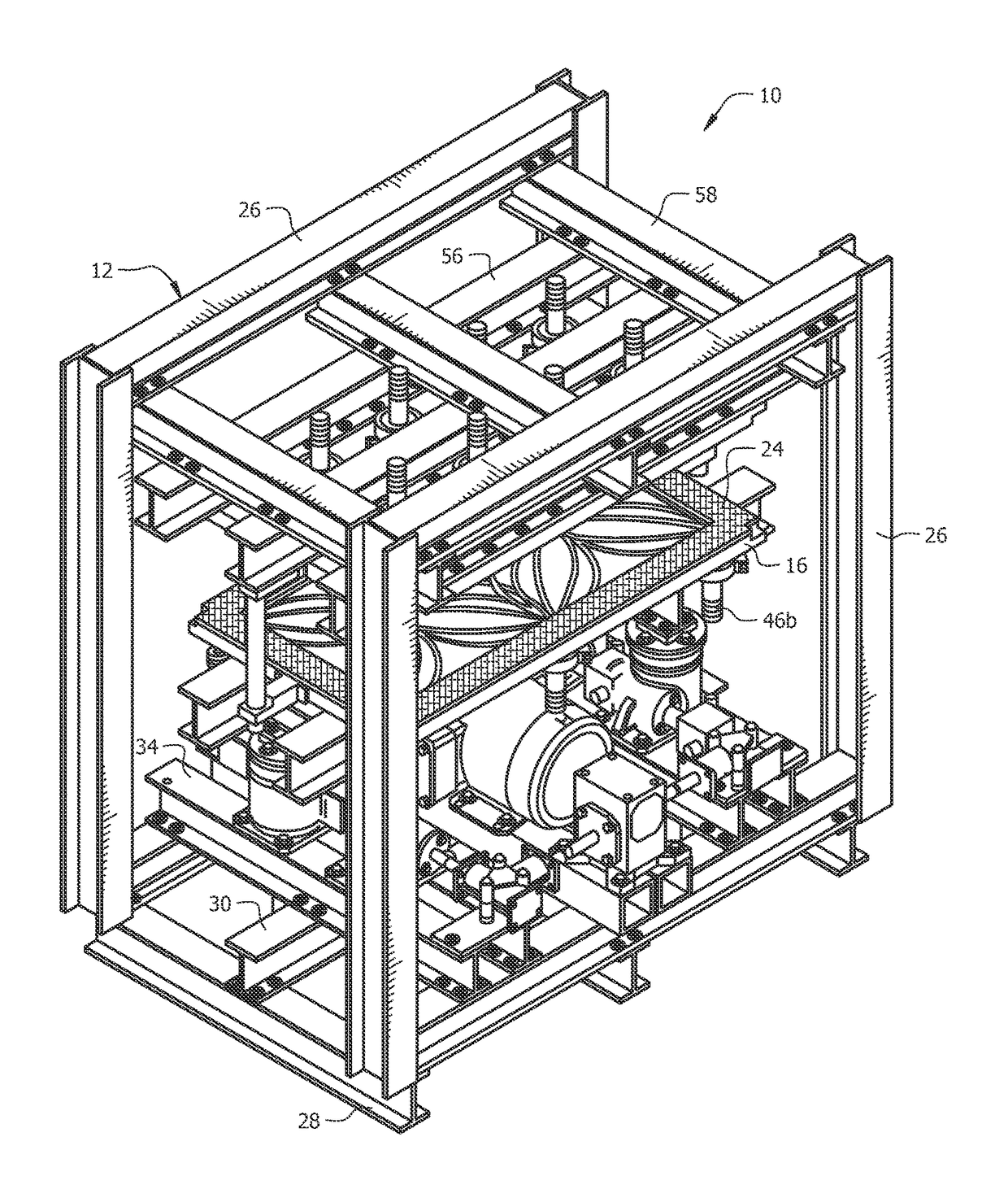
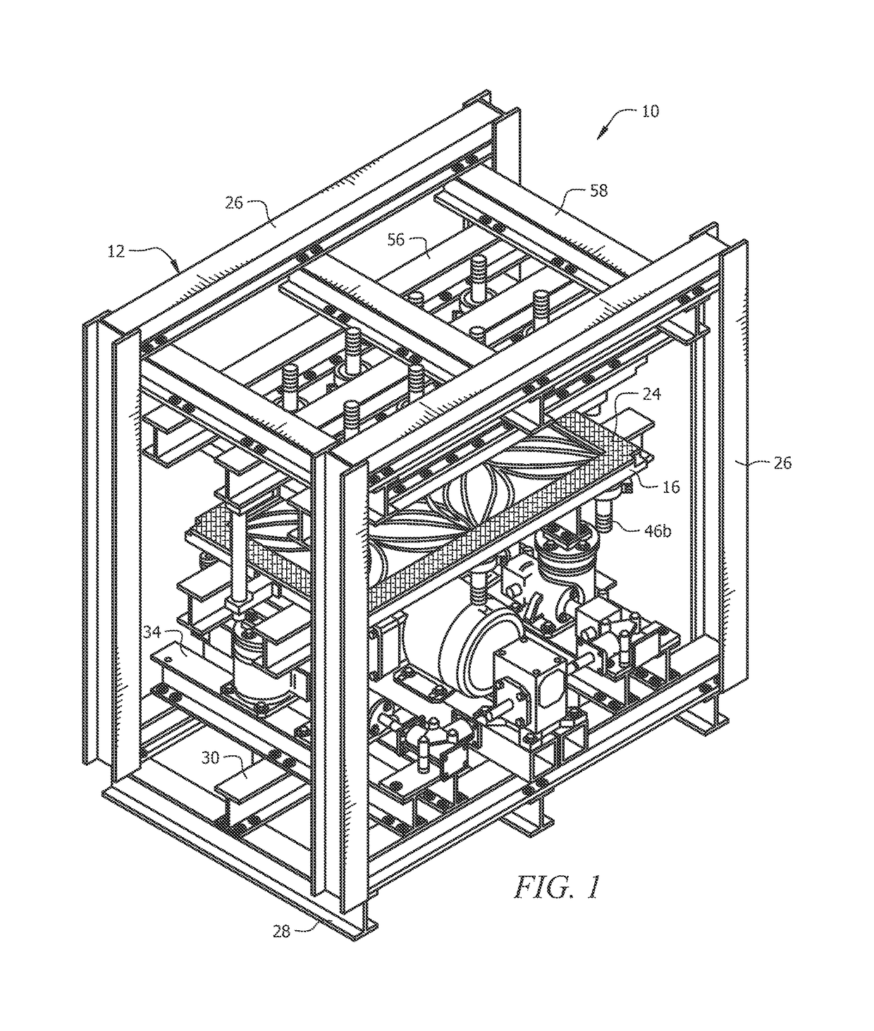
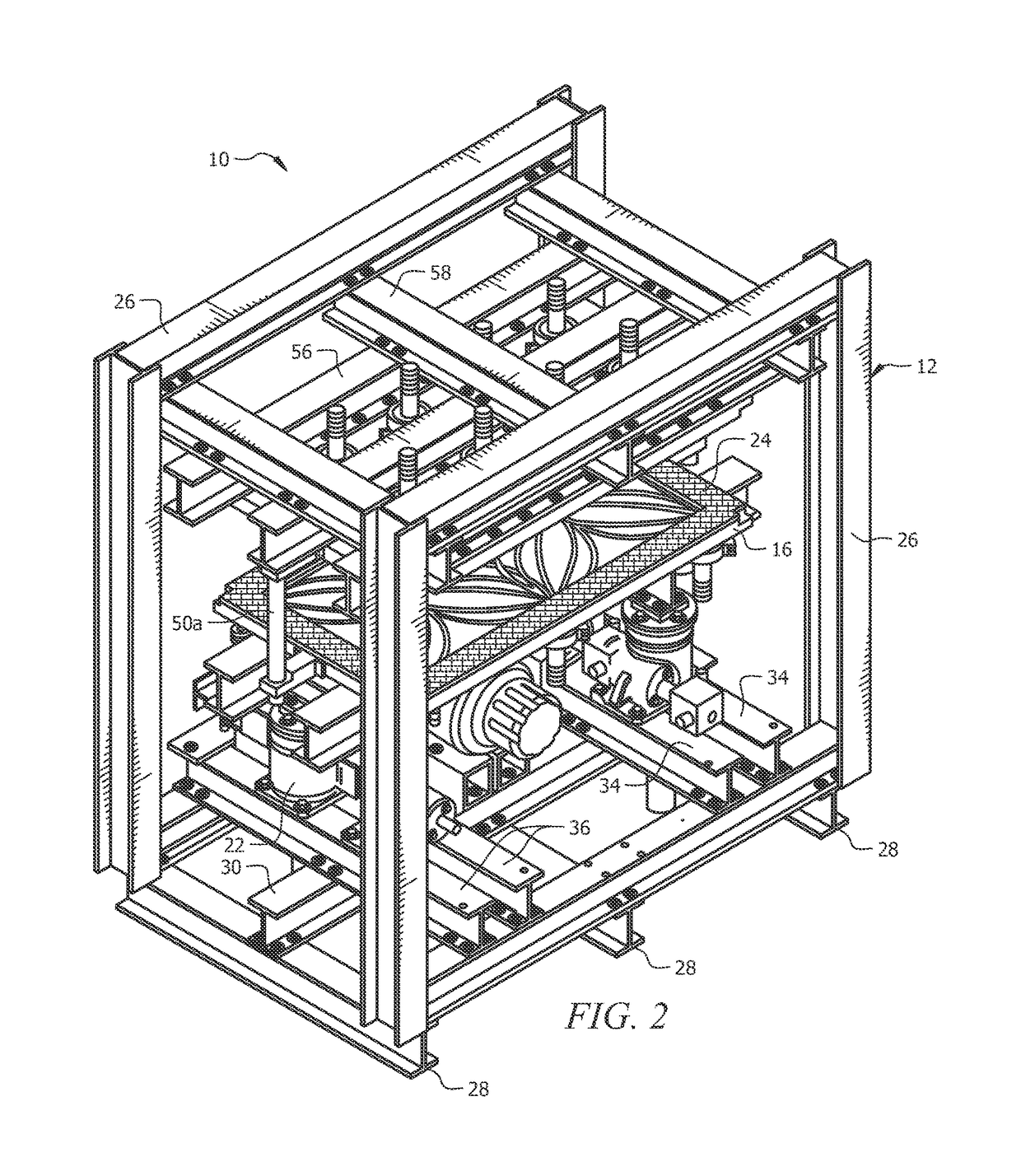
[0058]Structure 10 depicted in FIGS. 1-7 is a preferred structure. The front and rear perspective views of FIGS. 1 and 2 disclose frame 12 to which the various parts are mounted but those parts are best seen in the exploded view of FIG. 7. Upper platen 14, lower platen 16, fine filter media 18, nanoparticles 20, jack screws 22, gasket 24 and the other main elements of the invention can be connected to one another in many different ways and on differing frames and not just in the specific ways on the particular frame depicted.

[0059]Referring therefore to FIG. 7, there it will be seen that structural side frames 26, 26 are rectangular in this preferred embodiment and are positioned parallel to one another in respective vertical planes. They are longitudinally disposed as drawn relative to transversely disposed, equidistantly spaced apart I-beams, collectively denoted 28, that form the foundation of novel batch-automated microfiltration press 10 and which overlie a floor, a table top, ...


PUM


Abstract

A batch-automated microfiltration press for producing large uniform thickness nanomaterial sheets includes a filtration envelope of variable size that is defined between an upper platen having a fixed position and a lower platen disposed in spaced apart, parallel relation to the upper platen. The upper platen has a plurality of input nozzles and a plurality of flow dispersers associated with each of the input nozzles. Nanoparticles are deposited onto a fine filter membrane positioned in the filtration envelope. Flow channels and drain holes are formed in the lower platen. Each of the flow channels has a non-linear path of travel. A closed-loop fluid control system maintains a predetermined rate of nanoparticle deposition onto the fine filter membrane. A motion control system controls the raising and the lowering of the lower platen, maintaining a constant displacement instead of constant pressure, enabling the production of clean, undamaged sheets of nanomaterial papers.

Description

BACKGROUND OF THE INVENTION1. Field of the Invention[0001]This invention relates to the fabrication of large uniform thickness sheets of nanomaterials, including micro-fibrillated cellulose, nano-crystalline cellulose, carbon fibers, nanotubes, nanofibers, and nanoparticles of other sources including but not limited to graphene, boron nitride nanotubes, quantum dots, fullerenes, and the like.2. Description of the Prior Art[0002]Nanomaterials can possess much greater strength, conductivity, surface area, and other attractive properties at a much lower weight than standard engineering materials such as wood, metals, plastics, and the like.[0003]It is difficult to produce large, freestanding sheets of such materials with high levels of purity and nanomaterial content. Conventional manufacturing processes such as solvent casting, vapor deposition and the like require the use of additives, binders, surfactants and adhesives which reduce the purity and nanomaterial content, and thereby re...

Claims


Application Information

Patent Timeline
IPC IPC(8): D21J3/12B30B9/02B30B1/00
CPCB30B9/02B30B1/00D21J3/12B30B9/06
Inventor HIPOL, PHILIP J.HALDANE, DAVID
Owner INNOVATECH ENG
Learn More