Thermoelectric heat transferring system

a technology of thermal energy transfer and thermal element, applied in the field of thermal systems, can solve the problems of relative limited cooling capacity of the thermal element of the cooling system, malfunction or negative, and achieve the effect of minimizing thermal heat loss

Inactive Publication Date: 2018-02-13
ZELISSEN MARCUS JOZEF GERTRUDIS
View PDF7 Cites 3 Cited by
  • Summary
  • Abstract
  • Description
  • Claims
  • Application Information

AI Technical Summary

Benefits of technology

[0010]arranging minimized thermal heat loss ...

Problems solved by technology

A problem associated with such known systems is that the thermoelectric element for the cooling system has a relative limited cooling capacity due to the limited heat transferring capacity what is often done with conduction and further on and/or otherwise by convection.
Suppressing this problem by i...

Method used


Image

  • Thermoelectric heat transferring system
  • Thermoelectric heat transferring system
  • Thermoelectric heat transferring system

Examples


Embodiment Construction

Legends of the Figures

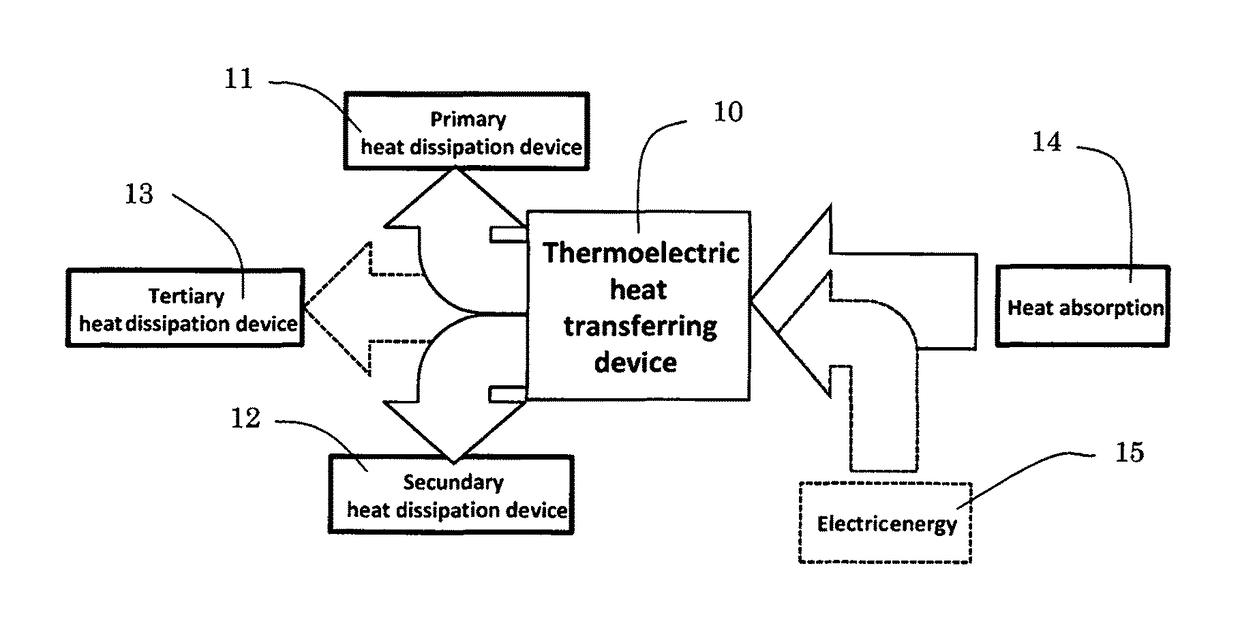
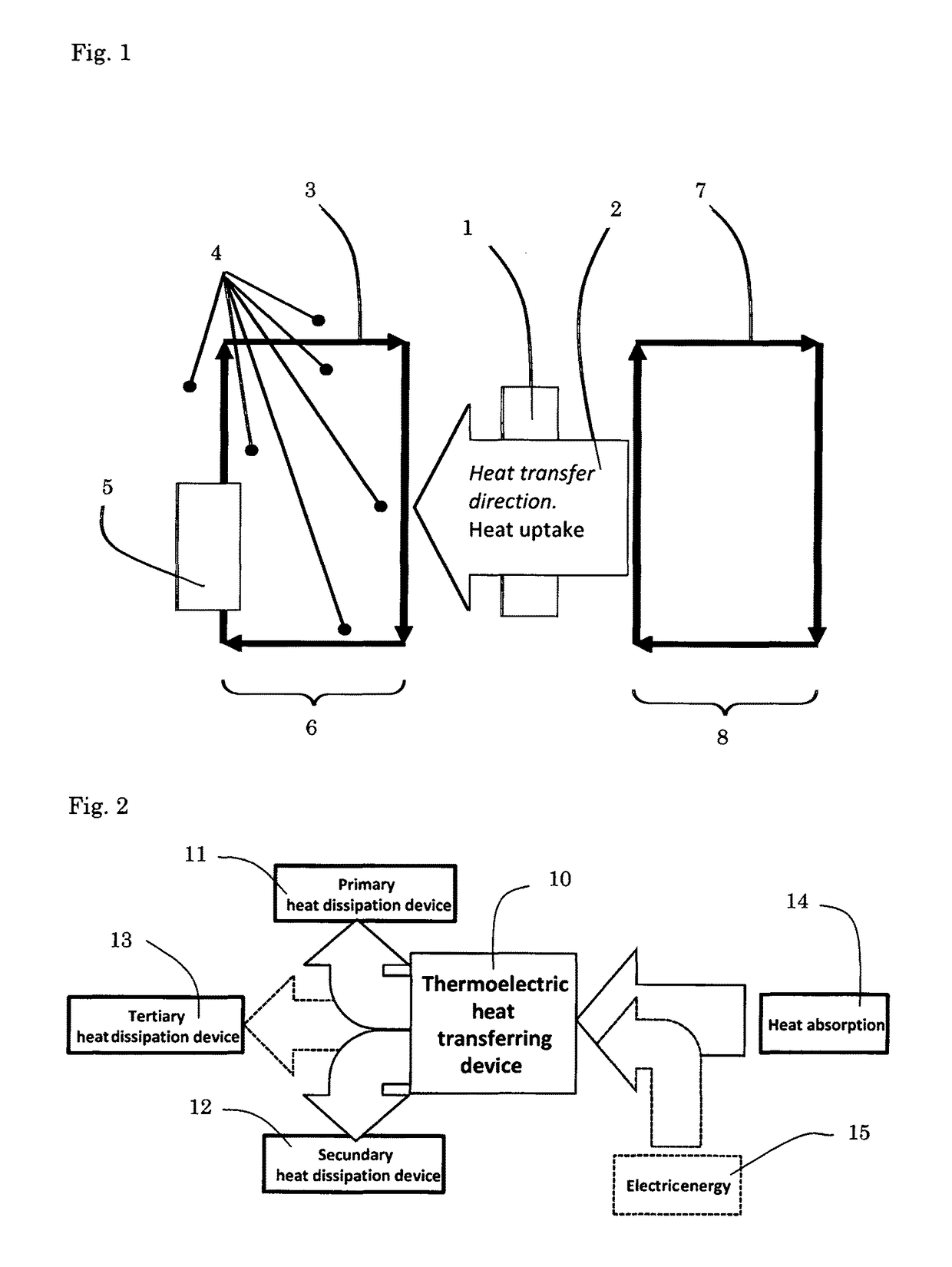
[0058]1. Thermoelectric element[0059]2. Heatflux through thermoelectric element[0060]3. Cooling channel primary loop[0061]4. Surroundings cooling channel[0062]5. Heat dissipation device[0063]6. Primary loop[0064]7. Cooling channel secondary loop[0065]8. Secondary loop[0066]10. Thermoelectric heat transferring device[0067]11. Primary heat dissipation device[0068]12. Secondary heat dissipation device[0069]13. Tertiary heat dissipation device[0070]14. Heat absorption[0071]15. Electric energy[0072]20. Thermoelectric heat exchanger[0073]21. Radiator with fan[0074]22. Central reservoir[0075]23. Phase change Material (PCM)[0076]24. Heat dissipation device (to release or absorb heat)[0077]25. Cooler (for example but not limited to vapour compression cooler)[0078]26. Inlet of new entering liquid[0079]27. Heat transferring system with heat exchanger[0080]28. Heat transferring system with heat exchanger from surrounding water[0081]29. Outlet of liquid (discharge to for ex...


PUM


Abstract

A thermal system, comprising a thermoelectric element arranged for a heat flux through the element from the cold side for heat uptake to the hot side for heat dissipation, wherein the heat uptake of the thermoelectric element is arranged by convention, the system further comprising a primary loop for accommodating a cooling liquid for transferring the heat away of the thermoelectric element, wherein the thermoelectric element is arranged for having a maximum heat transfer capacity being higher than the maximum heat dissipation capacity of the primary loop and/or wherein the system is arranged for, manipulation of the flow which affects the stagnant film layer at the heat transmitting surface of the thermoelectric element of the forced convection, to enhance the heat transfer coefficient, and/or wherein a part of the primary loop forms a liquid channel for the heat transmitting surface of the thermoelectric element wherein the direction of the flow is traversing the direction of the liquid flow of the opposite side of the thermoelectric element.

Description

[0001]This application is the national stage of PCT / NL2013 / 000006, filed Feb. 25, 2013.FIELD OF THE INVENTION[0002]The invention relates to a thermal system provided with thermo electric elements, were the invention describes the conditions to accomplish enhanced and improved thermal heat transfer of the thermoelectric elements to create an overall better performing thermal system. The invention is in particular applicable and useful in thermoelectric systems where is made use of thermal heat transfer by means of convection with a liquid flow. The solution is even more applicable for a thermoelectric assembly wherein there is direct contact of the liquid to the thermoelectric elements that are embedded in flexible manner for maintaining reliability, durability and good lifetime as known from the invention WO02086980.Background of the Invention[0003]Such system can be used as cooling system or heating system, depending of which heat flux direction is chosen for the thermoelectric ele...

Claims


Application Information

Patent Timeline
IPC IPC(8): F25B21/00H01L35/32F25B21/02F25B21/04F25B25/00
CPCF25B21/04H01L35/32F25B21/02F25B25/005H10N10/17
Inventor ZELISSEN, MARCUS JOZEF GERTRUDIS
Owner ZELISSEN MARCUS JOZEF GERTRUDIS
Why Eureka
Try Eureka