
Liquid ejecting head and manufacturing method for liquid ejecting head

a technology of liquid ejecting head and manufacturing method, which is applied in the direction of printing, inking apparatus, etc., can solve the problems of warping, long path member that is attached to the liquid ejecting head provided with a plurality of liquid ejecting units, and the flow path member is generated, etc., to suppress reaction force, reduce rigidity, and suppress the effect of base member distortion

Active Publication Date: 2018-02-13
SEIKO EPSON CORP
View PDF7 Cites 1 Cited by
  • Summary
  • Abstract
  • Description
  • Claims
  • Application Information

AI Technical Summary

Benefits of technology

This configuration effectively suppresses distortion of the base member and maintains the precise positioning of nozzles, ensuring accurate liquid droplet landing and reducing the size of the liquid ejecting head by stabilizing the connection and allowing for easier assembly and heat dissipation.

Problems solved by technology

Therefore, during formation, there is a concern that warping is generated in the flow path member.
In particular, the flow path member that is attached to the liquid ejecting head provided with a plurality of liquid ejecting units tends to be long and warping tends to occur.
Therefore, when the reinforcing member is attached to the base member by the screw and the like, there is a concern that the base member is distorted in response to reaction force that is received from the reinforcing member.
When the base member is distorted, there is a concern that the posture of the liquid ejecting unit is changed and the position of the nozzle is deviated from a prearranged position.
As a result, there is a concern that a landing position of liquid droplets that are ejected from the nozzle toward the recording medium is deviated from the prearranged position.

Method used


Image

  • Liquid ejecting head and manufacturing method for liquid ejecting head
  • Liquid ejecting head and manufacturing method for liquid ejecting head
  • Liquid ejecting head and manufacturing method for liquid ejecting head

Examples


Embodiment Construction

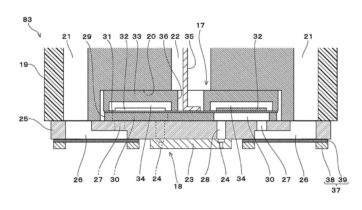
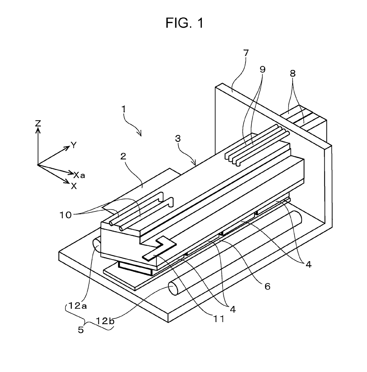
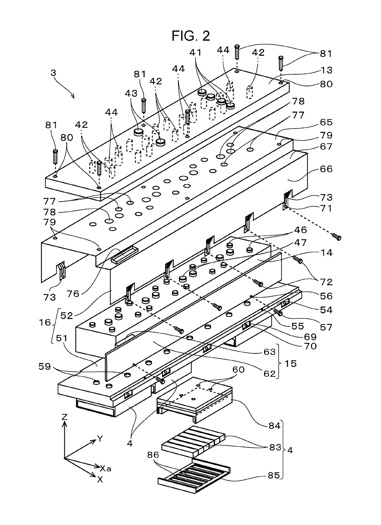
[0037]Embodiments of the invention will be described below with reference to the drawings. Note that, in the embodiments described below, there are various limitations as preferred specific examples of the invention, but the scope of the invention is not limited to these aspects unless particular limitations of the invention are otherwise stated in the explanation below. In addition, in the description below, an ink jet recording head (hereinafter, recording head) 3 that is mounted on an ink jet printer (hereinafter, printer) 1 which is one type of a liquid ejecting apparatus is given as an example of the liquid ejecting head of the invention.

[0038]The configuration of the printer 1 will be described with reference to FIG. 1. The printer 1 is an apparatus which performs recording of an image or the like by ejecting ink in liquid form on the front surface of a recording medium 2 such as recording paper. The printer 1 is provided with the recording head 3 that is provided with a plura...


PUM


Abstract

A liquid ejecting head includes a liquid ejecting unit that has a nozzle surface to which the nozzle is open, a base member to which the liquid ejecting unit is fixed, and a cover member that is attached to the base member and on which a laminated member is laminated, in which the cover member has a fixing portion to which the laminated member is fixed and a fragile portion that has lower rigidity than the fixing portion, and is attached to the base member by fixing the fragile portion to the base member.

Description

[0001]The entire disclosure of Japanese Patent Application No: 2016-074968, filed Apr. 4, 2016 is expressly incorporated by reference herein in its entirety.BACKGROUND1. Technical Field[0002]The present invention relates to a liquid ejecting head such as an ink jet recording head that ejects liquid from a nozzle and a manufacturing method for the liquid ejecting head.2. Related Art[0003]For example, there is an image recording apparatus such as an ink jet printer or an ink jet plotter as a liquid ejecting apparatus on which a liquid ejecting head is mounted, but the liquid ejecting head is also applied to various manufacturing apparatuses by taking advantage of a recent feature in which it is possible to accurately land a very small amount of liquid at a predetermined position. For example, the liquid ejecting head is applied to a display manufacturing apparatus which manufactures a color filter of a liquid crystal display or the like, an electrode forming apparatus which forms an e...

Claims


Application Information

Patent Timeline
Patent Type & Authority Patents(United States)
IPC IPC(8): B41J2/14
CPCB41J2/1433B41J2/14233B41J2002/14362B41J2002/14419B41J2202/19B41J2202/20
Inventor KINOSHITA, RYOTANAWANO, MASAHISA
Owner SEIKO EPSON CORP
Learn More