
Surgical sponge and needle counter

a needle container and sponge technology, applied in the field of surgical sponge and needle container, can solve the problems of time-consuming process, costing the facility money and the surgeon valuable time, and achieve the effect of saving and costing the surgeon more tim

Active Publication Date: 2018-02-06
VARIAMED
View PDF18 Cites 5 Cited by
  • Summary
  • Abstract
  • Description
  • Claims
  • Application Information

AI Technical Summary

Benefits of technology

The system enhances safety and efficiency by facilitating accurate counting and reducing the risk of sharps injuries, thereby improving surgical safety and reducing costs associated with miscounts and injury prevention.

Problems solved by technology

The sponges can hind to one another, causing a miscount.
This is a time consuming process costing the facility money and the surgeon valuable time.

Method used


Image

  • Surgical sponge and needle counter
  • Surgical sponge and needle counter
  • Surgical sponge and needle counter

Examples


first embodiment

[0037]the invention is shown in FIGS. 1-15.

[0038]The counter comprises a sponge tray 10, a needle tray 12 which nests in the sponge tray, and a cover 14 over the needle tray. These elements are initially held together by a shrink-wrap band at the perimeter of the trays.

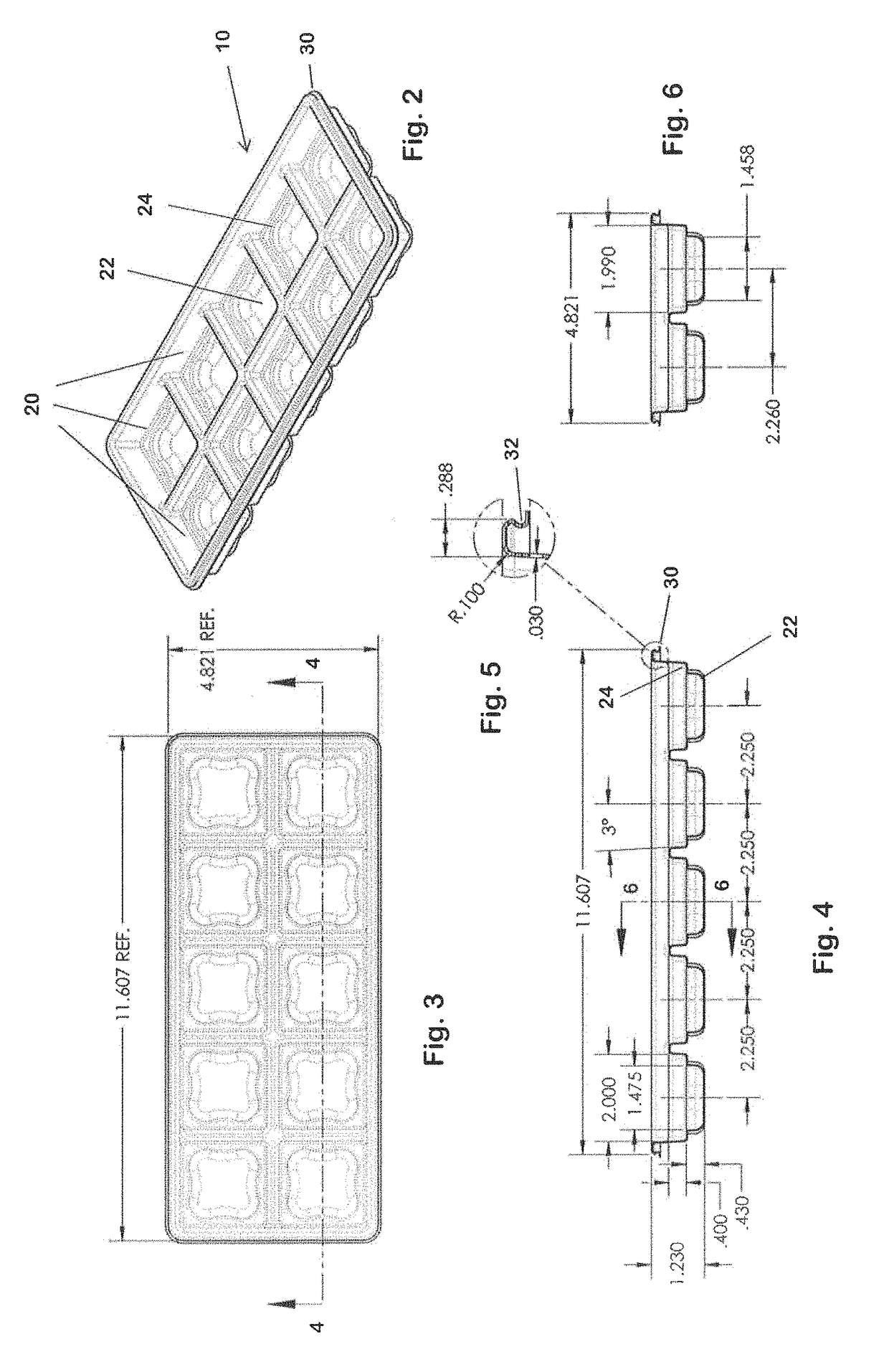
[0039]The sponge tray 10 (FIGS. 2-6) is a unitary molded plastic tray defining ten wells 20. The tray initially contains ten lap sponges (not shown), one in each well. After a sponge is used, the tech should replace it in a well.

[0040]Each well 20 has a recess 22 at the bottom to receive fluids, as described below. Each recess is smaller than the sponge-receiving portion of the well, so there is a ledge 24 extending around each recess. The sponges rest on the ledges, above the recesses.

[0041]The sponge tray 10 has a peripheral flange 30 which reinforces the tray. The flange is formed so as to define a groove 32 extending along the outer periphery of the tray.

[0042]The sponge tray is substantially transparent, so that ...


PUM


Abstract

A surgical sponge counter includes a unitary molded plastic sponge tray defining a plurality of wells each sized to hold a lap sponge. Each well has a ledge defining a recess below the sponge for collecting fluid once the sponge is replaced in the tray. A needle counting receptacle tray may be nested within the sponge tray above the sponges.

Description

[0001]This application claims benefit of provisional patent application 62 / 130,057, filed Mar. 9, 2015.BACKGROUND OF THE INVENTION[0002]This invention relates to a surgical sponge and needle container.[0003]Frequently, sponges are piled onto a table or into a container during an operation. Post procedure, medical personnel attempt to count, the sponges. The sponges can hind to one another, causing a miscount.[0004]It has been reported that seventy-four percent of all needle / sharps injuries occur as a result of passing a needle / sharp. Some form of “safety zone” for sharps is required by the joint commission in every facility.[0005]Whenever a miscount of needles / sharps or sponges occurs, a lengthy process must be performed to insure there is no URFO (unintended retention of foreign objects). This is a time consuming process costing the facility money and the surgeon valuable time.[0006]This invention aims to help medical personnel avoid sharps injuries, and get a proper count of sharp...

Claims


Application Information

Patent Timeline
Patent Type & Authority Patents(United States)
IPC IPC(8): A61B50/33A61B50/36A61B50/37A61M5/32A61B50/00A61B50/30A61B90/00
CPCA61B50/33A61B50/362A61B50/37A61M5/3205A61B2090/0804A61B2050/3006A61B2050/3008A61B2050/3009A61B2050/375A61B2050/005
Inventor SELLERS, DAVID
Owner VARIAMED
Learn More