
Artificial salivary gland

a salivary gland and artificial technology, applied in the field of artificial salivary gland devices or assemblies, can solve the problem that no other technology can generally restore normal salivary flow, and achieve the effect of restoring normal salivary flow, constant background rate, and higher rate during eating

Active Publication Date: 2018-01-23
UNIV OF CONNECTICUT
View PDF5 Cites 8 Cited by
  • Summary
  • Abstract
  • Description
  • Claims
  • Application Information

AI Technical Summary

Benefits of technology

[0010]In exemplary embodiments, the present disclosure provides assemblies that substantially restore normal saliva flow, along with important salivary functions, especially anti-caries function. The saliva-like fluid can flow at a constant background rate during rest, swallowing with incidental tooth contact and at a higher rate during eating. No other technology can generally restore normal salivary flow.
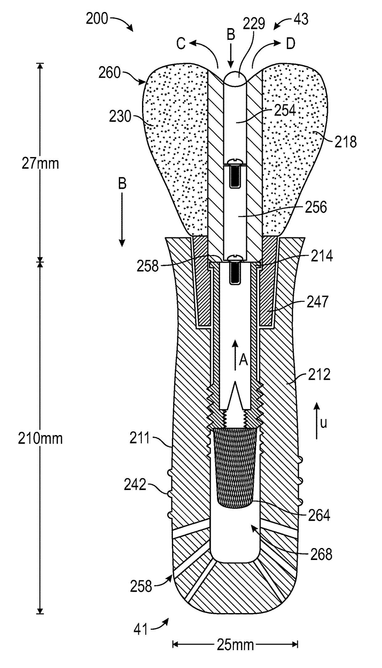
[0020]The present disclosure also provides for a salivary gland assembly wherein the insert member includes an outer chamber in fluid communication with the fluid; and wherein when tooth contact forces of the user engage the insert member, the outer chamber is pressurized, thereby causing fluid to flow through the insert member and out of an outlet of the insert member and into an oral cavity of the user. The present disclosure also provides for a salivary gland assembly further including a valve member associated with the insert member; and wherein when the tooth contact forces cease engaging the insert member, the valve member closes and creates a vacuum in the outer chamber, thereby drawing additional fluid of the user into the outer chamber. The present disclosure also provides for a salivary gland assembly wherein the insert member includes one or more spring members; and wherein when the tooth contact forces cease engaging the insert member, the one or more spring members facilitate the closing of the valve member.

Problems solved by technology

No other technology can generally restore normal salivary flow.

Method used


Image

  • Artificial salivary gland
  • Artificial salivary gland
  • Artificial salivary gland

Examples


example 1

[0120]Based on results from an in vivo rabbit study it is noted that: (i) sufficient interstitial / marrow fluid exists for the exemplary assemblies (e.g., assemblies 10, 100, 200) to work, likely with only one implant / assembly (e.g., 10, 100, 200) needed per patient; (ii) there is some positive fluid pressure available necessitating a lower vacuum pressure in the assembly (e.g., 25% to 50% of atmospheric was sufficient to extract 0.05 milliliters of fluid per minute); (iii) the implant wall (e.g., wall 11) does not need to be significantly porous, a limited number of small holes (e.g. approximately 30 holes at 0.5 mm diameter in wall 11) may be sufficient; (iv) holes in wall 11 may not need to be obturated at the first surgery.

[0121]FIGS. 14-17 are photos / images showing an exemplary prototype used in an initial rabbit study. These prototypes were made in a machine shop by hollowing-out an implant member (e.g., Straumann implant, 12 mm, 4.1 mm), adding holes in the endosseous portion,...


PUM


Abstract

Artificial salivary gland devices and assemblies are provided. The present disclosure provides artificial salivary pump / gland devices and assemblies, and related methods of use. One embodiment utilizes the interstitial / marrow fluid reservoir within the underlying mandibular or maxillary bone as a source for replacement saliva. The salivary pump / assembly, which is implantable in the mandibular or maxillary bone as a dental implant and driven by incidental tooth contact and masticatory forces, harvests interstitial / marrow fluid and treats it via semi-permeable membrane technology and soluble particles as a continuously available saliva replacement. Masticatory forces and tooth contact power the pump to both harvest interstitial / marrow fluid and drive flow through a bed of ion-exchange resins and / or soluble particles to adjust fluid chemistry providing a continuously available saliva-like solution. Exemplary devices and assemblies can also be utilized to introduce beneficial bacteria into the oral cavity and / or be utilized as a delivery system for drugs / therapeutic agents.

Description

CROSS-REFERENCE TO RELATED APPLICATIONS[0001]This application claims the benefit of U.S. Provisional application entitled “Improved Artificial Salivary Gland,” which was filed on Mar. 24, 2015, and assigned Ser. No. 62 / 137,397, the contents of which are herein incorporated by reference in their entirety.FIELD OF THE DISCLOSURE[0002]The present disclosure relates to salivary gland devices or assemblies and, more particularly, to artificial salivary gland devices or assemblies and related methods of use.BACKGROUND OF THE DISCLOSURE[0003]As many as 20 million individuals in the U.S. alone cannot make sufficient saliva for normal function and comfort, a condition called xerostomia. The vast majority of these (about 16 million) have xerostomia as a side-effect of prescription medications, another 4 million due to Sjögren's Syndrome and approximately 300,000 become xerostomic each year secondary to head and neck radiation for cancer. Aside from discomfort and pain, related to chronically ...

Claims


Application Information

Patent Timeline
Patent Type & Authority Patents(United States)
IPC IPC(8): A61C13/08A61C8/00A61F2/02A61C19/06A61F2/28A61C5/50
CPCA61F2/022A61C8/00A61C8/0018A61C13/08A61C19/06A61F2/2803A61C19/063A61F2220/0033A61C5/50A61C8/003A61C8/0039A61C8/0037
Inventor KELLY, JOHN ROBERTADAMS, DOUGLAS J.FREILICH, MARTIN ALLEN
Owner UNIV OF CONNECTICUT
Learn More