
Sucker rod apparatus and methods for manufacture and use

a technology of pumping system and sucking rod, which is applied in the direction of drilling pipes, screw threads, other domestic articles, etc., can solve the problems of reducing pumping efficiency, breaking the sucking rod and coupling, and costly repairs, so as to improve the wear resistance, reduce the amount of capital investment, and improve the effect of wear resistan

Active Publication Date: 2018-01-16
RFG TECH PARTNERS LLC
View PDF7 Cites 36 Cited by
  • Summary
  • Abstract
  • Description
  • Claims
  • Application Information

AI Technical Summary

Benefits of technology

The invention provides a system of sucker rod components that are stronger, more resistant to wear, and can be easily integrated into existing sucker rod systems. The components can be made from fiber-reinforced thermosetting plastics that have increased wear resistance and can be reused. The use of magnets in the system reduces corrosion, scaling, viscosity, and pumping efficiency, improving overall oil and gas production. The invention also provides a method for making sucker rod segments with molded-on rod guides and sleeves that increase wear resistance and reduce the amount of resin used. The invention also includes a rod string comprising rod string segments with molded-on rod guides, centralizing magnet rod inserts, and couplings with molded-on guides. These components provide for ready manufacture and installation and are long-lasting, magnetic, and reconditionable.

Problems solved by technology

Lengthy sucker rod strings frequently abrade against the side of the production tubing and can wear the tubing and the sucker rod string and may result in breaking the rods and couplings.
Pumping efficiency is reduced by frictional losses and down time for repairs and the repairs can be costly.
Water and other fluids can impede the free flow of natural gas, especially in the casing surrounding the production tube.

Method used


Image

  • Sucker rod apparatus and methods for manufacture and use
  • Sucker rod apparatus and methods for manufacture and use
  • Sucker rod apparatus and methods for manufacture and use

Examples


Embodiment Construction

[0056]The invention will now be described more fully hereinafter with reference to the accompanying drawings, in which some, but not all concepts of the invention are illustrated. Indeed, the invention may be embodied in many different forms and should not be construed as limited to the examples set forth herein; rather, the embodiments provided in this disclosure are intended to satisfy applicable legal requirements.

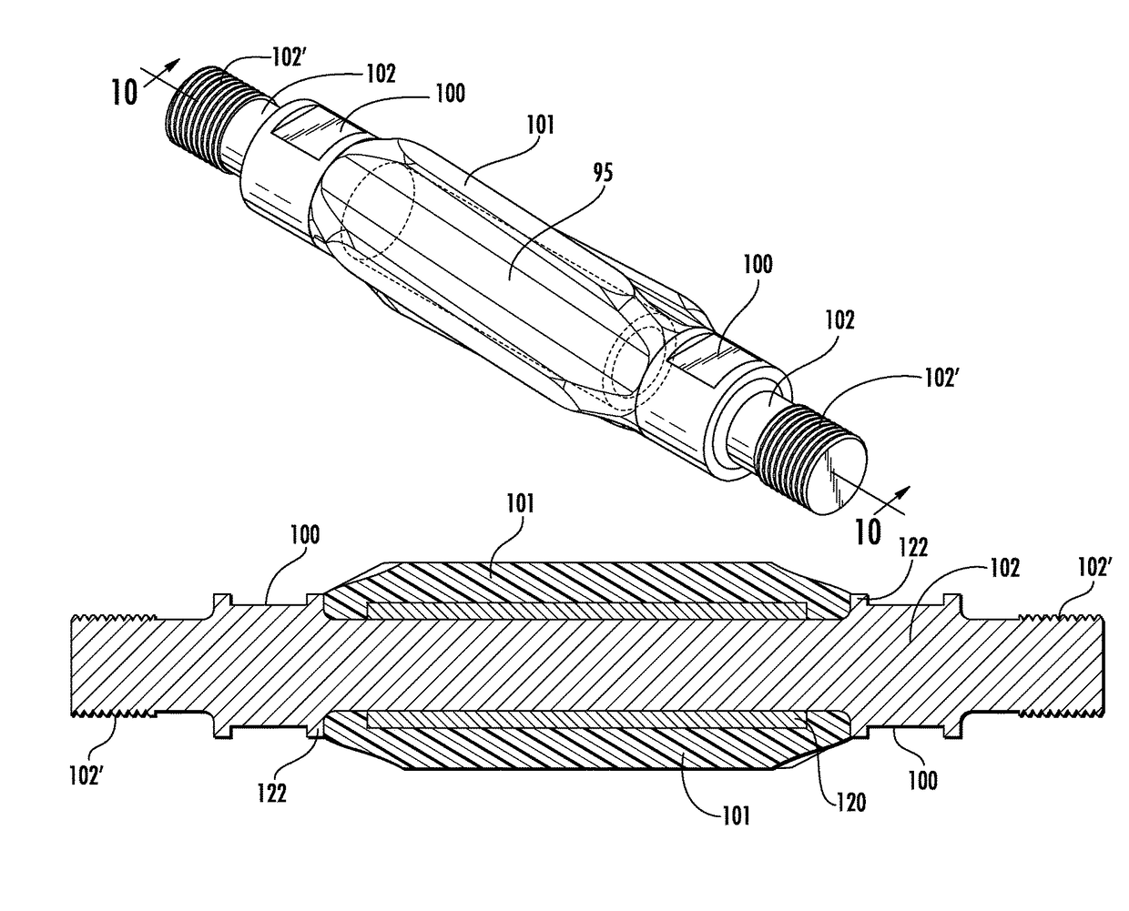
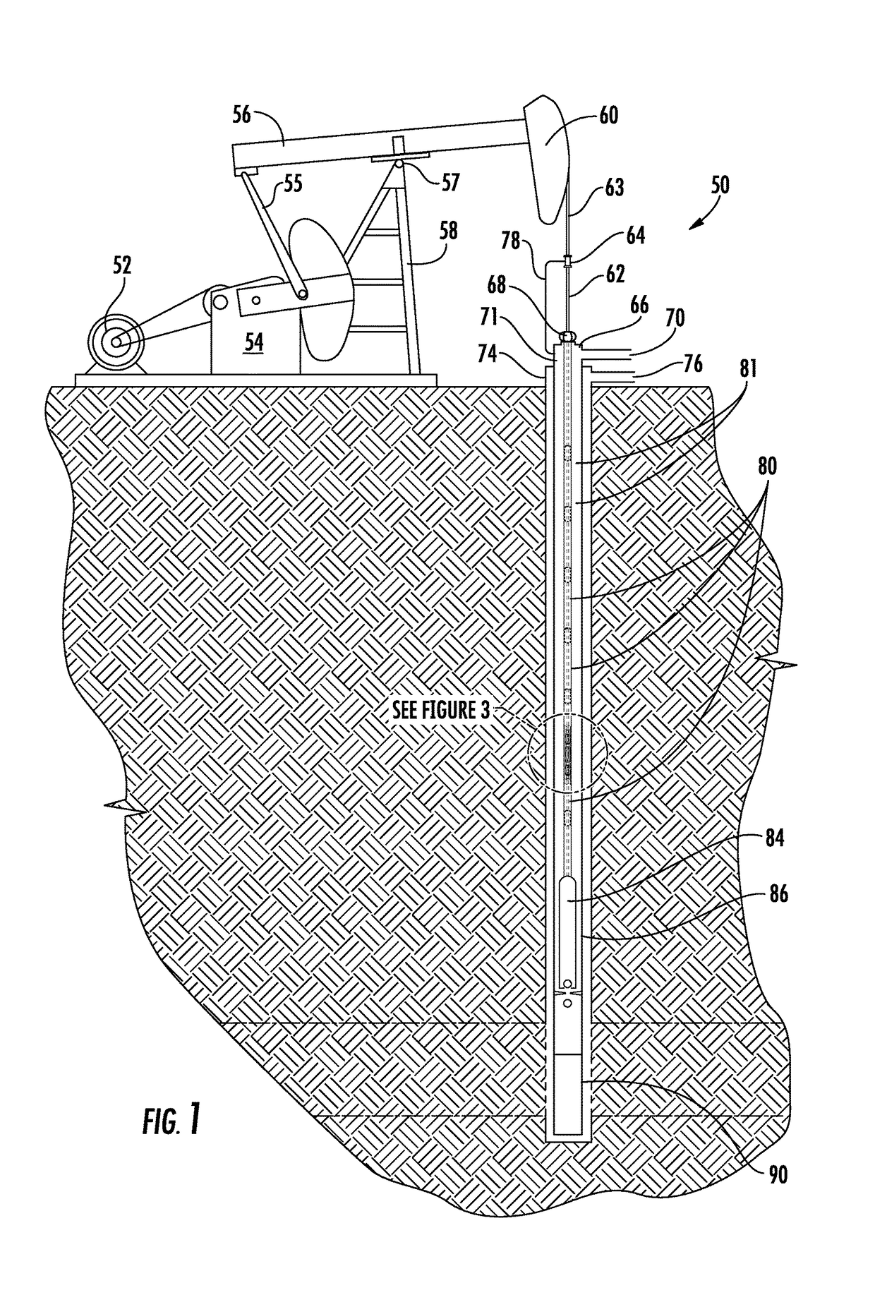
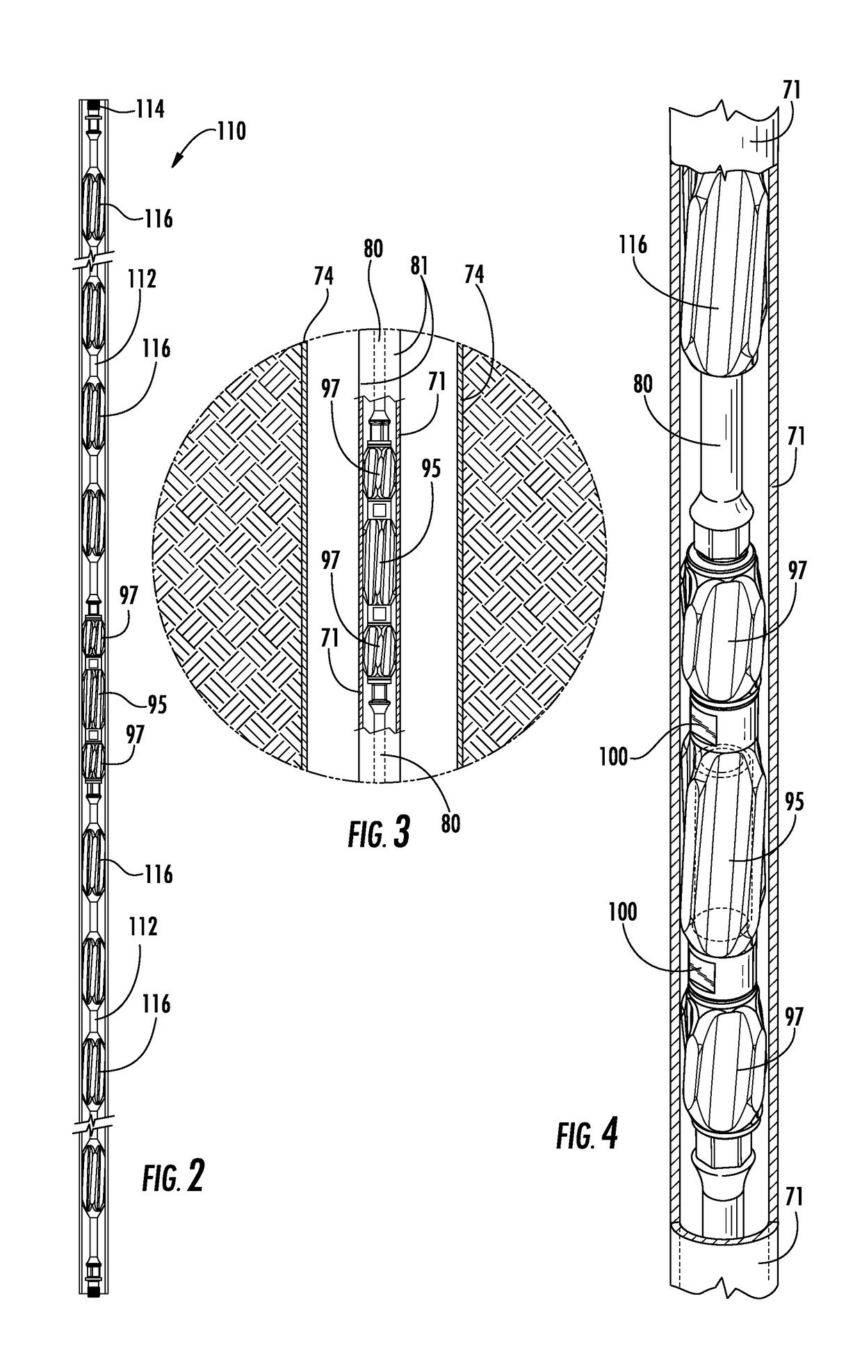
[0057]FIG. 1 illustrates generally at 50 a sucker-rod pumping system having a motor 52 acting as a prime mover and generating rotational motion. The motor 52 may be powered by electricity, diesel fuel, propane, gasoline, or any other source of power. A gear reducer 54 reduces the speed of rotation and provides the torque necessary to drive the sucker-rod pumping system. The gear reducer connects a counterbalanced crank arm 55 to a walking beam 56 mounted on Samson posts 58. The walking beam pivots up and down about saddle bearing 57, converting the rotational movement o...


PUM

PropertyMeasurementUnit
lengthaaaaaaaaaa
lengthaaaaaaaaaa
lengthaaaaaaaaaa

Abstract

A sucker rod string improved by the use of wear resistant, high temperature resistant, fiber-reinforced phenolic composite materials as centralizing guides on sucker rods and couplings, both molded on the rod and prepared as snap-on couplings for in-the-field use, and on magnet rod inserts, both rod box and pin magnet rod inserts, in which the thermosetting composites are used as sleeves, encapsulating housings, and centralizing guides. The magnet rod inserts and couplings are designed to be machined so that worn phenolic composite can be removed and replaced with fresh composite without removing or damaging the magnet. Processes are disclosed for integrating composite thermoset molding into sucker rod, coupling, and magnet rod insert manufacture and for refurbishing used components of a sucker rod string.

Description

CROSS-REFERENCE TO RELATED APPLICATION[0001]This application claims the benefit of priority based on U.S. Provisional Patent Application Ser. No. 61 / 662,422 filed in the United States Patent and Trademark Office on Jun. 21, 2012, entitled “Sucker Rod Apparatus And Methods For Manufacture And Use,” which is hereby incorporated by reference in its entirety.FIELD OF THE INVENTION[0002]This invention relates to sucker rod pumping systems of the type commonly used to extract crude petroleum and natural gas from underground reservoirs; more specifically, the invention relates to methods of manufacturing and using sucker rod components and to modifications and attachments to the sucker rod system to improve overall well performance.BACKGROUND OF THE INVENTION[0003]Sucker-rod pumping is a long established method for artificially lifting crude petroleum and natural gas. In oil wells and in free-flowing gas wells, sucker rod pumping is used to lift liquids in the well, including crude oil in ...

Claims


Application Information

Patent Timeline
Patent Type & Authority Patents(United States)
IPC IPC(8): E21B17/10E21B17/00E21B17/02
CPCE21B17/00E21B17/02E21B17/1042E21B17/10E21B17/042E21B17/1071B21H3/04B21J5/08
Inventor MARTIN, JONATHAN R.
Owner RFG TECH PARTNERS LLC
Learn More