Drive mechanism of a drug delivery device

a technology of driving mechanism and drug delivery device, which is applied in the direction of medical devices, intravenous devices, other medical devices, etc., can solve the problems of difficult operation of dose setting and dose dispensing procedure, large size of dose indicating numbers, and difficulty in identifying patients, so as to achieve easy and unequivocal reading

Inactive Publication Date: 2018-01-09
SANOFI SA
View PDF5 Cites 0 Cited by
  • Summary
  • Abstract
  • Description
  • Claims
  • Application Information

AI Technical Summary

Benefits of technology

[0010]It is therefore an object of the present invention to avoid disadvantages of known drug delivery devices and to provide a drive mechanism of a drug delivery device allowing for an intuitive operation, both for setting and for dispensing of a dose. It is another object to provide a dose indicating mechanism which is easy and unequivocal to read even for persons suffering impaired vision.
[0020]The mutual engagement of drive sleeve, piston rod and dispensing sleeve allows for a rather compact and robust design of the drive mechanism. Due to the switching function and the torque transmission function of the dispensing sleeve, the overall number of parts the drive mechanism is assembled of can be reduced. This way, mechanical tolerances of the mutually interacting components of the drive mechanism can be reduced.
[0033]For instance, the dispensing sleeve comprises at least one, preferably at least two diametrically oppositely located radially outwardly extending and axially elongated notches or grooves at an inside wall portion in which correspondingly shaped and radially outwardly extending protrusions or pins of the piston rod are received. In this way, a permanent rotational engagement between dispensing sleeve and piston rod can be attained while the dispensing sleeve is displaceable in axial direction relative to the piston rod.
[0038]Hence, drive sleeve and dispensing sleeve are at least partially interleaved. In this way, dispensing sleeve and drive sleeve may mutually mechanically stabilize. Moreover, the dispensing sleeve and the drive sleeve may comprise axially extending guiding structures by way of which a well defined axial mutual displacement of drive sleeve and dispensing sleeve can be realized. In this way, a mutual and selective torque transmitting coupling of drive sleeve and dispensing sleeve can be attained.
[0065]The dose indicating mechanism is typically arranged inside the housing of the drive mechanism in such a way, that the dose indicating tape extending between first and second spools shows up below a dose indicating window of the housing. Since the dose indicating tape is selectively coiled up onto first and second spools, the tape can be rather long and may provide almost unlimited space for printing numbers thereon. The numbers presented on the dose indicating tape may therefore be comparatively large allowing for a good visibility and for a sufficient and unequivocal reading, even by patients or users suffering impaired vision.
[0077]The same may apply with the single dose limiting member during a dose setting procedure. When the single dose limiting member abuts with the radially outwardly extending radial stop of the drive sleeve, the drive sleeve cannot be further rotated in a dose setting direction. Consequently, a dose setting procedure will be limited and stop. In this way, setting of a dose exceeding a predefined dose size of e.g. 120 I.U. can be effectively prevented.

Problems solved by technology

For instance, with patient's suffering chronic diseases, such like diabetes, the patient may be physically infirm and may also have impaired vision.
Moreover, a dose setting as well as a dose dispensing procedure must be easy to operate and has to be unambiguous.
Due to the rather compact design and limited geometrical dimensions of such drug delivery devices the size of such dose indicating numbers is fairly small.
For visually impaired persons reading of such tiny numbers may therefore be rather difficult.

Method used


Image

  • Drive mechanism of a drug delivery device
  • Drive mechanism of a drug delivery device
  • Drive mechanism of a drug delivery device

Examples


Embodiment Construction

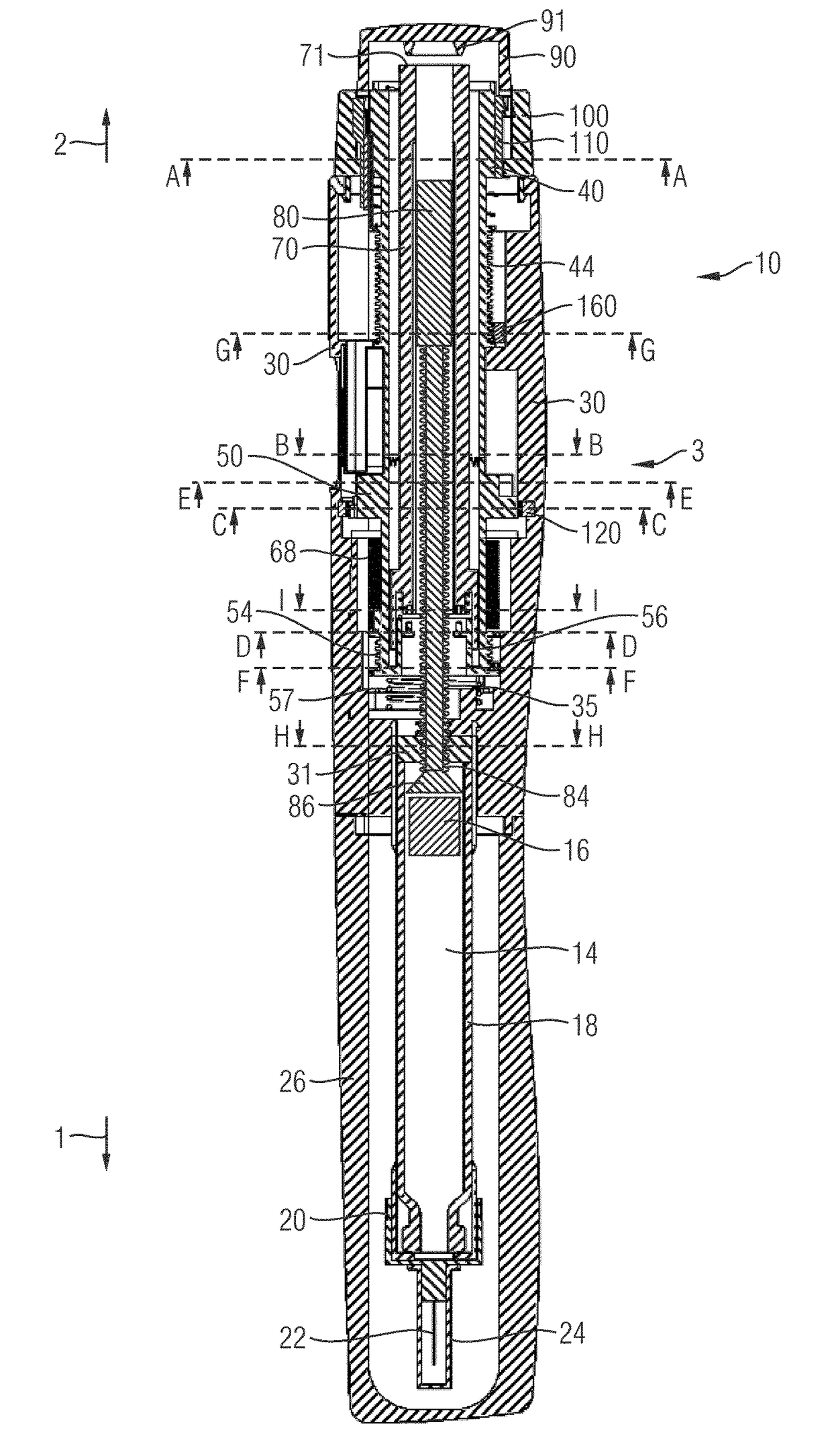
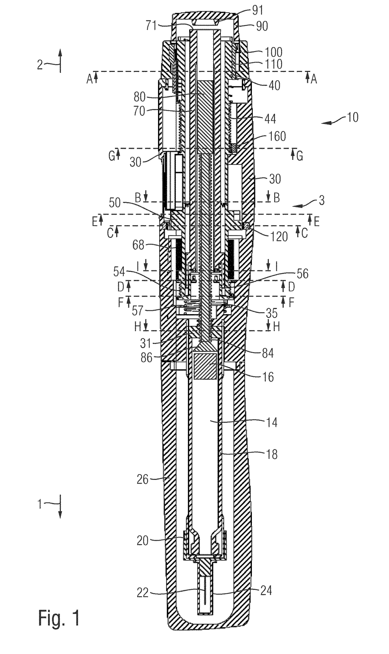
[0182]In FIGS. 1, 10 and 26 the drive mechanism 3 of a drug delivery device 10 is illustrated in an assembled and in an exploded view, respectively. The drug delivery device 10 is of pen-injector type and comprises a substantially cylindrical and axially elongated shape. Throughout the Figures the axial distal direction is denoted with reference number 1 and the opposite proximal direction is denoted with reference number 2. The drug delivery device 10 comprises a proximal housing component 30 to receive the drive mechanism 3.

[0183]In distal direction 1, the housing 30 is connected with a cartridge holder 12 which is adapted to accommodate and to receive a cartridge 14 containing the medicament to be dispensed by the drug delivery device 10. The cartridge 14 typically comprises a vitreous barrel 18 of cylindrical shape which is sealed in distal direction 1 by a pierceable sealing member, such like a septum.

[0184]In proximal direction 2, the cartridge 14 is sealed by a piston 16 slid...


PUM


Abstract

A drug delivery device for dispensing a dose of a medicament includes an elongated housing extending in an axial direction, and a piston rod to operably engage with a piston of a cartridge to displace the piston in a distal axial direction. The drug delivery device further includes a drive sleeve extending in an axial direction and being rotatable against the action of a spring during a dose setting procedure and a dispensing sleeve rotatably engaged with the piston rod and being displaceable in an axial direction relative to the drive sleeve to engage with the drive sleeve in a torque transmissive way during a dose dispensing procedure.

Description

CROSS-REFERENCE TO RELATED APPLICATIONS[0001]This application is a national stage application under 35 U.S.C. §371 of International Patent Application No. PCT / EP2014 / 056972, filed on Apr. 8, 2014, which claims priority to EP 13163072.5, filed on Apr. 10, 2013. The entire contents of each of the foregoing applications are incorporated herein by reference.[0002]The present invention relates to a drive mechanism for a drug delivery device and to a respective drug delivery device. In particular, the invention relates to an injection device such like a pen-type injector inter alia comprising a single and / or a last-dose limiting mechanism and further comprising a comparatively large dose indicating display.BACKGROUND AND PRIOR ART[0003]Drug delivery devices for setting and dispensing a single or multiple doses of a liquid medicament are as such well-known in the art. Generally, such devices have substantially a similar purpose as that of an ordinary syringe.[0004]Drug delivery devices, in...

Claims


Application Information

Patent Timeline
Patent Type & Authority Patents(United States)
IPC IPC(8): A61M5/00A61M5/315
CPCA61M5/3158A61M5/31541A61M5/31548A61M5/31585A61M5/31593A61M2205/581A61M5/31553A61M5/31563A61M5/31568
Inventor BAYER, STEFANBERNING, DANIELBLANK, PHILIPPEPELZER, WOLFGANGPFOSER, MICHAELWILDEN, BJORN
Owner SANOFI SA
Why Eureka
Try Eureka