Eureka AIR delivers breakthrough ideas for toughest innovation challenges, trusted by R&D personnel around the world.

Methods of delivery of flexible heart valves

a flexible heart valve and valve frame technology, applied in the field of implantable prosthetic valves and valve frames, can solve the problems of high morbidity and mortality rates associated with surgical repair, high mortality rates during surgery or shortly after, so as to reduce the number of sutures, improve durability, and quick implantation

Active Publication Date: 2018-01-09
EDWARDS LIFESCIENCES CORP
View PDF419 Cites 11 Cited by
  • Summary
  • Abstract
  • Description
  • Claims
  • Application Information

AI Technical Summary

Benefits of technology

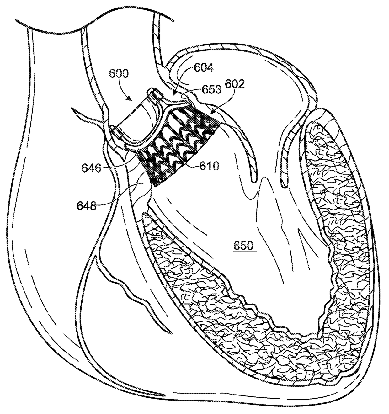
[0018]Disclosed embodiments of a prosthetic heart valve can be both radially collapsible (and therefore suitable for minimally invasive surgical techniques) and provide for relatively quick implantation (e.g., without sutures or with a reduced number of sutures required for implantation). Disclosed embodiments can also exhibit flexibility in response to physiologic loading, thereby potentially increasing durability as compared to, for example, conventional transcatheter heart valves. Thus, disclosed embodiments of prosthetic heart valves can be implanted using small surgical incisions (e.g., via a thoracotomy) and few or no sutures for anchoring to a patient's valve. Disclosed embodiments can combine the ability of surgical valves to undergo deflection or flexion during physiologic loading with the ability of transcatheter valves to be radially compressed for minimally invasive delivery methods. These and other advantages of the disclosed embodiments can result in quicker healing, less scarring, and reduced procedure times in some instances, as well as increased durability of the valve due at least partially to the valve's flexibility under physiologic loading.
[0020]In some embodiments, the wireform portion can comprise a plurality of cusps (e.g., three cusps) each configured to engage with a respective valve leaflet. Each of the cusps can comprise a thinned portion configured to facilitate compression of the wireform portion. For example, each of thinned portions of the cusps can provide a point of least resistance to bending, thereby facilitating collapse or compression of the valve as a whole, and specifically of the wireform portion.
[0024]The stent portion of some embodiments can comprise a circumferential strut adjacent the wireform portion. Additionally or alternatively, the stent portion can comprise a plurality of vertical struts extending from an inflow end of the stent portion toward the wireform portion. In some embodiments, the vertical struts can be spaced apart from one another, positioned between adjacent upright struts, and can terminate at the circumferential strut, if present. Disclosed embodiments can comprise a flexible skirt (e.g., a fabric skirt, such as a polyester skirt) coupled to the stent portion and configured to prevent leakage through the stent portion. A skirt can be positioned on the inside and / or outside of the stent portion lumen (e.g., one or more flexible skirts can be coupled to the inner surface of the stent portion and / or to the outer surface of the stent portion). Additionally or alternatively, the prosthetic valve can include a sealing ring coupled to the wireform portion, the sealing ring being configured to be positioned supraannularly.
[0032]In some methods, the prosthetic heart valve includes a one-piece prosthetic heart valve frame. In some methods, delivering the prosthetic heart valve can comprise delivering the prosthetic heart valve transapically. In some methods, expanding the prosthetic heart valve can effectively anchor the prosthetic heart valve without suturing the valve to the native valve.
[0033]In other methods, a pre-crimped balloon expandable stent portion can be provided and configured to anchor the prosthetic heart valve to a patient's native valve. The pre-crimped stent portion can be coupled to a self-expanding wireform portion and a plurality of leaflets to form the prosthetic heart valve, and the stent portion and the wireform portion can be coupled to one another via a cloth-covered flexible leaflet support stent. In some methods, the diameter of the stent portion in an expanded configuration is greater than the diameter of the stent portion in a compressed configuration, and expansion of the stent portion can enable self-expansion of the wireform portion.

Problems solved by technology

One problem with surgical therapy is the significant insult it imposes on chronically ill patients and the associated high morbidity and mortality rates associated with surgical repair.
Because of the trauma associated with the procedure and the attendant duration of extracorporeal blood circulation, mortality rates during surgery or shortly thereafter typically have been high.
It is well established that risks to patients increase with the duration of extracorporeal circulation.
Due to such risks, a substantial number of patients with defective valves are deemed inoperable because their condition is too frail to withstand the procedure.
Because of drawbacks associated with conventional open-heart surgery, percutaneous and minimally-invasive surgical approaches are garnering intense attention.
In addition, suturing the complex, undulating periphery of the sewing band can be difficult and time consuming, as various parts of the valve can interfere with access to the sewing band.
Although the valves disclosed in the '418 and '845 patents could be collapsed and inserted through a small incision, such as a thoracotomy, it would be difficult to suture them to the native annulus through such a small incision due to the configuration of the sewing band.
However, these surgical valves disadvantageously cannot be radially collapsed any appreciable amount, and therefore are not suitable for minimally invasive surgery procedures.
Such suturing can be disadvantageous in that it is time consuming and difficult, thus extending the length of surgery.
Thus, the valve component disclosed in the Oba application is not collapsible for implantation through small surgical incisions.
Further, because the heart valve disclosed in the Oba application includes two separate frames, construction can be time consuming and costly.

Method used


Image

  • Methods of delivery of flexible heart valves
  • Methods of delivery of flexible heart valves
  • Methods of delivery of flexible heart valves

Examples


Embodiment Construction

[0078]As used in this application and in the claims, the singular forms “a,”“an,” and “the” include the plural forms unless the context clearly dictates otherwise. Additionally, the term “includes” means “comprises.” Although the operations of exemplary embodiments of the disclosed method may be described in a particular, sequential order for convenient presentation, it should be understood that the disclosed embodiments can encompass an order of operations other than the particular, sequential order disclosed. For example, operations described sequentially may in some cases be rearranged or performed concurrently. Further, descriptions and disclosures provided in association with one particular embodiment are not limited to that embodiment, and may be applied to any embodiment disclosed herein. Moreover, for the sake of simplicity, the attached figures may not show the various ways in which the disclosed system, method, and apparatus can be used in combination with other systems, m...


PUM


Abstract

A prosthetic heart valve can include a valve frame having a wireform portion and a stent portion. The wireform and stent portions can be undetachably coupled together via a plurality of upright struts so as to form a one-piece prosthetic heart valve frame. Alternatively, a self-expanding wireform portion and a balloon-expandable stent portion can be coupled together via one or more leaflets and a subassembly having a flexible leaflet support stent and a sealing ring. The wireform portion can include cusps and commissures configured to support a plurality of leaflets. The prosthetic valve can be radially collapsible for minimally invasive and / or transcatheter delivery techniques. Disclosed embodiments can also provide flexion of the wireform portion (e.g., of the commissures) in response to physiologic pulsatile loading when the valve is implanted in a patient's native valve annulus. Methods of making and using prosthetic heart valves are also disclosed.

Description

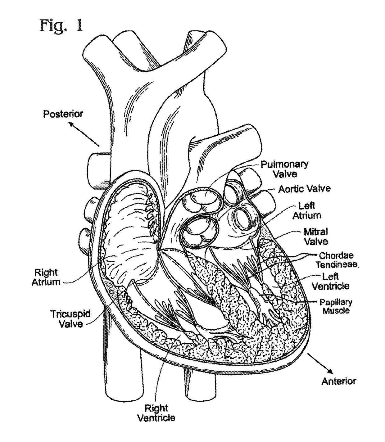
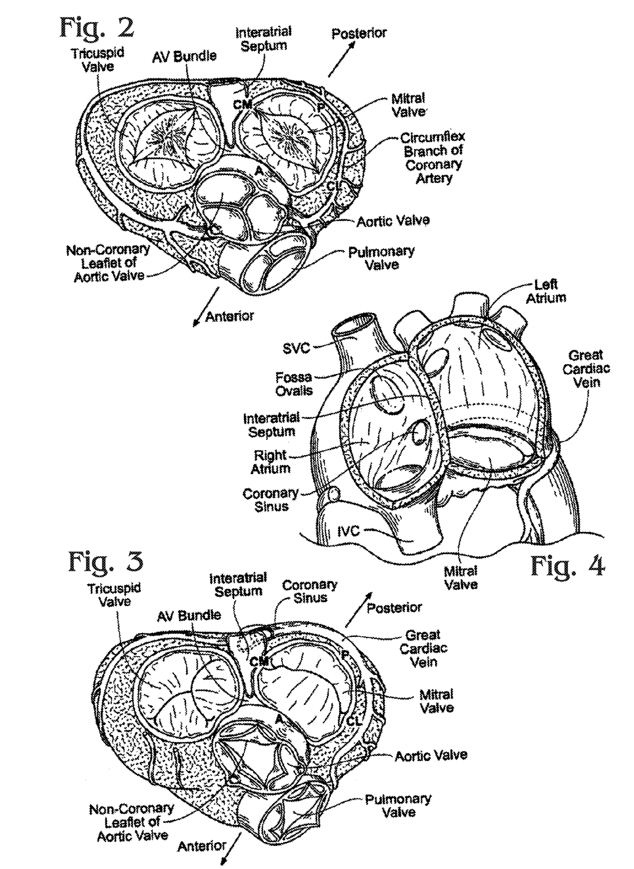
RELATED APPLICATIONS[0001]The present application is a divisional of U.S. application Ser. No. 13 / 237,556, now U.S. Pat. No. 8,845,720 filed Sep. 20, 2011, which in turn claims priority under 35 U.S.C. §119 to U.S. Provisional Application Ser. No. 61 / 386,833, filed Sep. 27, 2010, and Provisional Application Ser. No. 61 / 472,083, filed Apr. 5, 2011, all of which are incorporated by reference herein in their entirety.FIELD OF THE INVENTION[0002]The present invention concerns implantable prosthetic valves and valve frames, and related methods and systems, such as for example, prosthetic aortic valves that can be implanted using minimally invasive surgical techniques.BACKGROUND OF THE INVENTION[0003]In vertebrate animals, the heart is a hollow muscular organ having four pumping chambers as seen in FIG. 1: the left and right atria and the left and right ventricles, each provided with its own one-way valve. The natural heart valves are identified as the aortic, mitral (or bicuspid), tricus...

Claims


Application Information

Patent Timeline
Patent Type & Authority Patents(United States)
IPC IPC(8): A61F2/24
CPCA61F2/243A61F2/2412A61F2/2415A61F2/2418A61F2250/0071A61F2220/0075A61F2230/0054A61F2250/006A61F2250/0036A61F2/2433
Inventor CONKLIN, BRIAN S.
Owner EDWARDS LIFESCIENCES CORP
Why Eureka
Eureka Blog
Learn More