Sensor

a technology of sensors and electrodes, applied in the field of sensors, can solve the problems of lead wire deformation, difficulty in reducing the size or thickness of electrical terminals, lead wire deformation, etc., and achieve the effect of reducing the size or thickness

Active Publication Date: 2017-12-19
DENSO CORP
View PDF13 Cites 2 Cited by
  • Summary
  • Abstract
  • Description
  • Claims
  • Application Information

AI Technical Summary

Benefits of technology

[0015]When or after the sensor is installed in, for example, an exhaust pipe of an internal combustion engine, and the lead wires are pulled outside the sensor, an external force to pull each of the lead wires works as an external force to bend the spring bent portion through the spring connecting portion. The external force to bend spring bent portion acts as bending stress on the spring bent portion. This prevents both the external force which arises from the compression of the cylindrical cover and the external force which arises from the pulling of the lead wires from acting as tensile stress on the spring bent portion. This results in a decreased risk that the mechanical strength of the spring bent portion of the specific contact spring on which the stress easily concentrates reaches an upper limit thereof, thereby enabling the specific contact spring to have a required mechanical strength. This permits the contact springs to be made of a wire rod and reduced in size or thickness thereof.

Problems solved by technology

The crimping of the protective cylinder usually results in elastic deformation of the elastic sealing member, which leads to deformation of the lead wires.
The simultaneous application of the tension stresses to the boundaries results in need for increasing the mechanical strength of the electrical terminals, thus resulting in difficulty in reducing the size or thickness of the electrical terminals.
This causes the bush to be inwardly compressed, thereby leading to deformation of the lead wires.
This results in a decreased risk that the mechanical strength of the spring bent portion of the specific contact spring on which the stress easily concentrates reaches an upper limit thereof, thereby enabling the specific contact spring to have a required mechanical strength.

Method used


Image

  • Sensor
  • Sensor
  • Sensor

Examples


Embodiment Construction

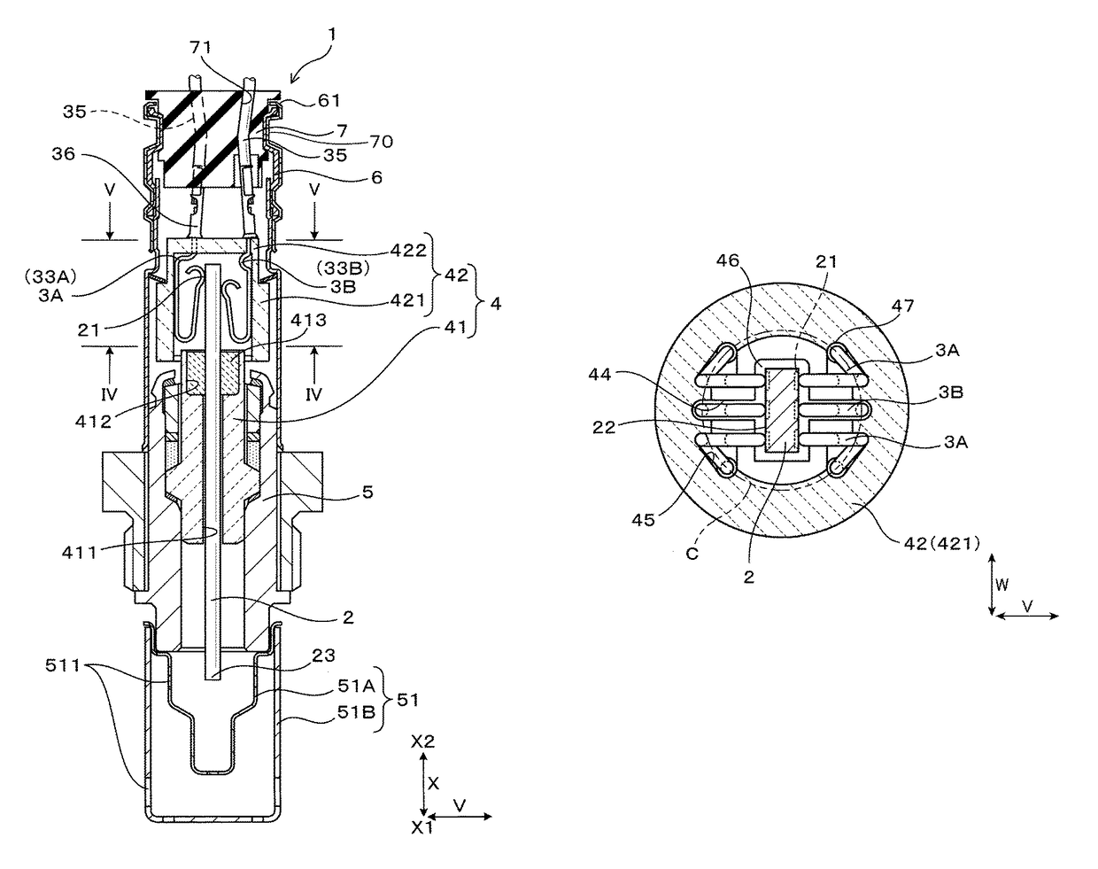
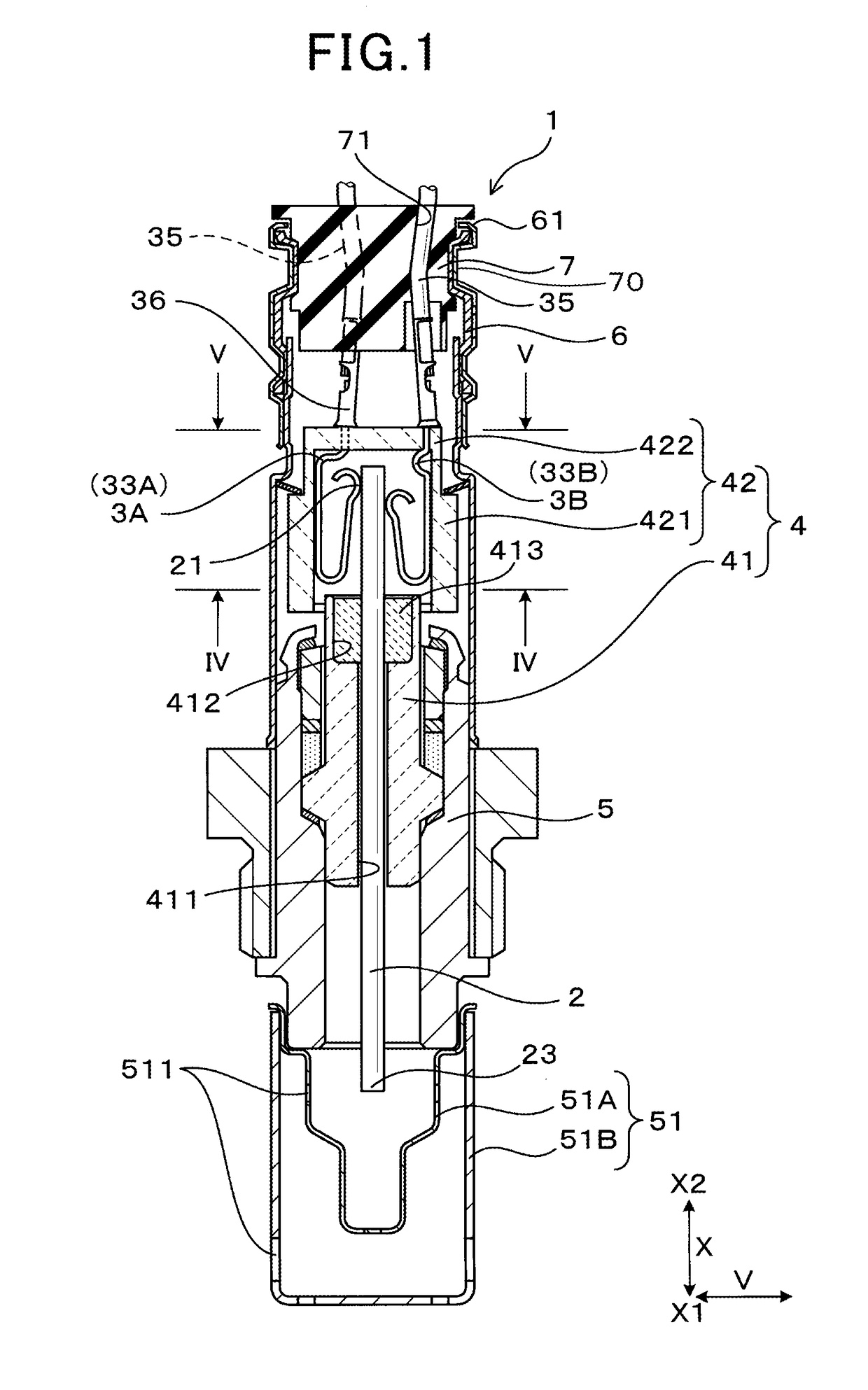
[0024]Referring now to the drawings, particularly to FIG. 1, there is shown the sensor 1 according to an embodiment.

[0025]The sensor 1, as illustrated in FIG. 1, includes the sensor device 2, a plurality of contact springs 3A and 3B, a plurality of lead wires 35, the porcelain insulator (also called a ceramic insulator) 4, the housing 5, the cylindrical cover 6, and the bush 7.

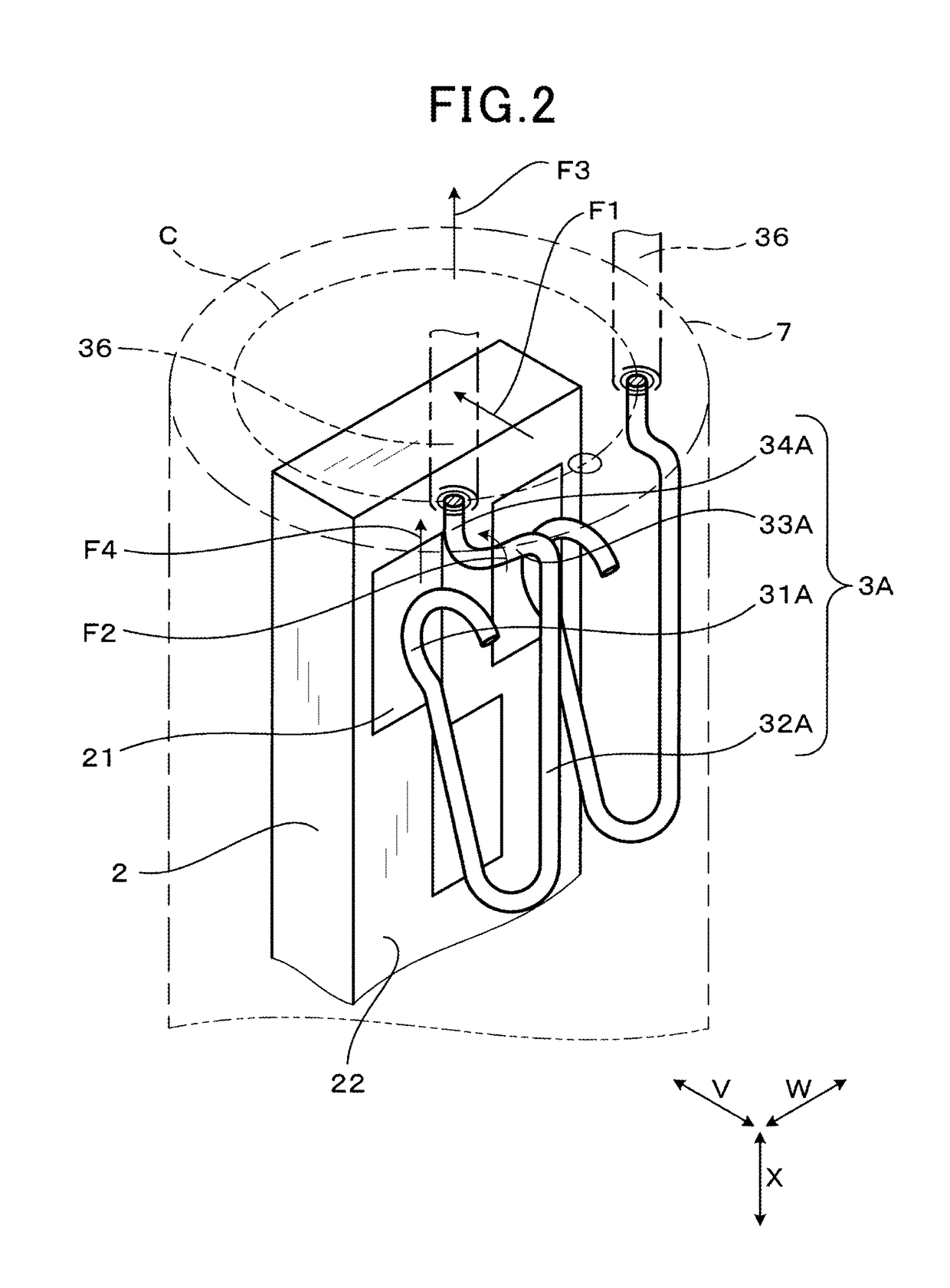
[0026]The sensor device 2 has major surfaces (which will also be referred to below as device surfaces) 22 which extend parallel to each other and are opposed through a thickness of the sensor device 2. The sensor device 22 also has a plurality of electrode terminals 21 disposed on the device surfaces 22, respectively. The contact springs 3A and 3B are placed in contact with the electrode terminals 21, respectively. The lead wires 35 are joined to the contact springs 3A and 3B, respectively. The porcelain insulator 4 has the sensor device 2 and the contact springs 3A and 3B retained therein. The housing 5 has t...


PUM


Abstract

A sensor includes contact springs placed in contact with electrode terminals on major surfaces of a sensor device. At least one of the contact springs includes a spring contact portion, a spring holding portion, a spring bent portion, and a spring connecting portion. The spring contact portion contacts an outer surface of one of the electrode terminals. The spring holding portion is turned from the spring contact portion and extends outside the spring contact portion so as to overlap the spring contact portion in the contacting direction. The spring bent portion is bent inwardly from the spring holding portion and extends at a given angle to the contacting direction. The spring connecting portion is bent from the spring bent portion and extends in the axial direction of the sensor. Such a structure enables the contact spring to be reduced in size and thickness without sacrificing a required mechanical strength thereof.

Description

CROSS REFERENCE TO RELATED DOCUMENT[0001]The present application claims the benefit of priority of Japanese Patent Application No. 2015-248533 filed on Dec. 21, 2015, the disclosure of which is incorporated herein by reference.BACKGROUND[0002]1 Technical Field[0003]This disclosure relates generally to a sensor designed to have a junction between an electrode terminal of a sensor device and a contact spring.[0004]2 Background Art[0005]Japanese Patent First Publication No. 2010-223615 teaches a gas sensor for use in measuring the concentration of a given gas component such as oxygen or NOx (nitrogen oxide) contained in exhaust emissions flowing through an exhaust pipe of an internal combustion engine. The gas sensor has a plurality of electrode terminals which are disposed on a sensor device and are connected to a plurality of electrical terminals in the form of contact springs joined to a plurality of lead wires, respectively. Each of the electrical terminals is made up of a terminal...

Claims


Application Information

Patent Timeline
Patent Type & Authority Patents(United States)
IPC IPC(8): H01R13/24H01R13/405G01M15/10H01R13/428H01R13/33
CPCH01R13/2407G01M15/104H01R13/428H01R13/405H01R13/33H01R13/2464
Inventor HINO, SATOSHI
Owner DENSO CORP
Why Eureka
Try Eureka