
Method for regulating driving stability

a technology of driving stability and electronic control device, which is applied in the direction of control device, driver input parameter, vehicle components, etc., can solve the problems that steering input can give rise to violent vehicle reactions, and achieve the effect of improving further the assistan

Active Publication Date: 2017-12-12
CONTINENTAL TEVES AG & CO OHG
View PDF10 Cites 2 Cited by
  • Summary
  • Abstract
  • Description
  • Claims
  • Application Information

AI Technical Summary

Benefits of technology

[0012]An aspect of the present invention aims to improve further the assistance provided to the driver during an avoidance process with respect to controllability by the driver and driving stability.
[0015]By traction control taking place on the basis of a first slip threshold value, which preferably lies in the range of 10%-20%, when a risk of collision which requires avoidance is detected, a reduction in the lateral forces which can be transmitted by the tire can be avoided. Therefore, in a first phase, the vehicle also follows the prescription of the driver directly and in an undamped way even in wet or snowy conditions when steering into the avoidance path.
[0016]As a result of the fact that in a second phase the traction control process takes place on the basis of a second slip threshold value which preferably lies in the range of 30%-50%, in this phase of the avoidance maneuver the lateral forces which can be transmitted are limited. This avoids “veering off” of the vehicle during which the yawing for the purpose of cutting out changes excessively quickly to yawing into the avoidance path, wherein high yawing accelerations occur. This could otherwise lead to oversteering and lateral positioning or even to tipping over of the vehicle. A further advantage is that a vehicle which has a tendency to understeer owing to the reduced lateral forces requires less space when cutting back into the avoidance lane than an oversteering vehicle, or a relatively narrow avoidance path is sufficient.
[0017]The first phase of the avoidance maneuver expediently starts when a risk of collision is detected, wherein the first phase does not start, in particular, until after turning in of the driver is detected. The customary anti-lock brake control or traction control can therefore be maintained for as long as possible with optimized transmission of longitudinal forces, at the cost of the lateral forces, in the sense of wide ranging braking of the vehicle.
[0018]It is advantageous if the second phase starts as soon as the driver steers counter to the avoidance direction, wherein the second phase preferably does not start until a measured steering angle speed and / or a measured yaw acceleration exceeds a predefined skidding threshold value. If the driver steers back and a lateral offset which is sufficient to avoid the obstacle has therefore been achieved, it is expedient to limit the lateral forces which can be transmitted, in particular at the front axle by applying a high brake step. In addition to shortening the braking distance to the stationary state, this prevents a build up of excessive lateral forces which endanger the driving stability and could lead to the vehicle rolling over. There can also be provision for this reduction in lateral force to be performed when, or only if, a rapid steering movement poses a particularly high risk to the driving stability. If the driver steers in a controlled fashion, the vehicle continues to follow his prescriptions directly and in an undamped fashion.
[0019]In the first phase a build up of braking force is preferably carried out at one or more wheels of the vehicle on the inside of the bend independently of the driver, in order to generate a yawing moment in the avoidance direction, wherein at least the brake slip at the intervention wheel or intervention wheels is limited. As a result of the fact that steering by the driver is assisted without a reduction in lateral forces, a lateral offset which is sufficient for the avoidance can be very quickly achieved.

Problems solved by technology

The intuitive steering input can be too dynamic for normal drivers who only experience emergency avoidance situations rarely, and said steering input can give rise to violent vehicle reactions, in particular during the subsequent steering back process.

Method used


Image

  • Method for regulating driving stability
  • Method for regulating driving stability
  • Method for regulating driving stability

Examples


Embodiment Construction

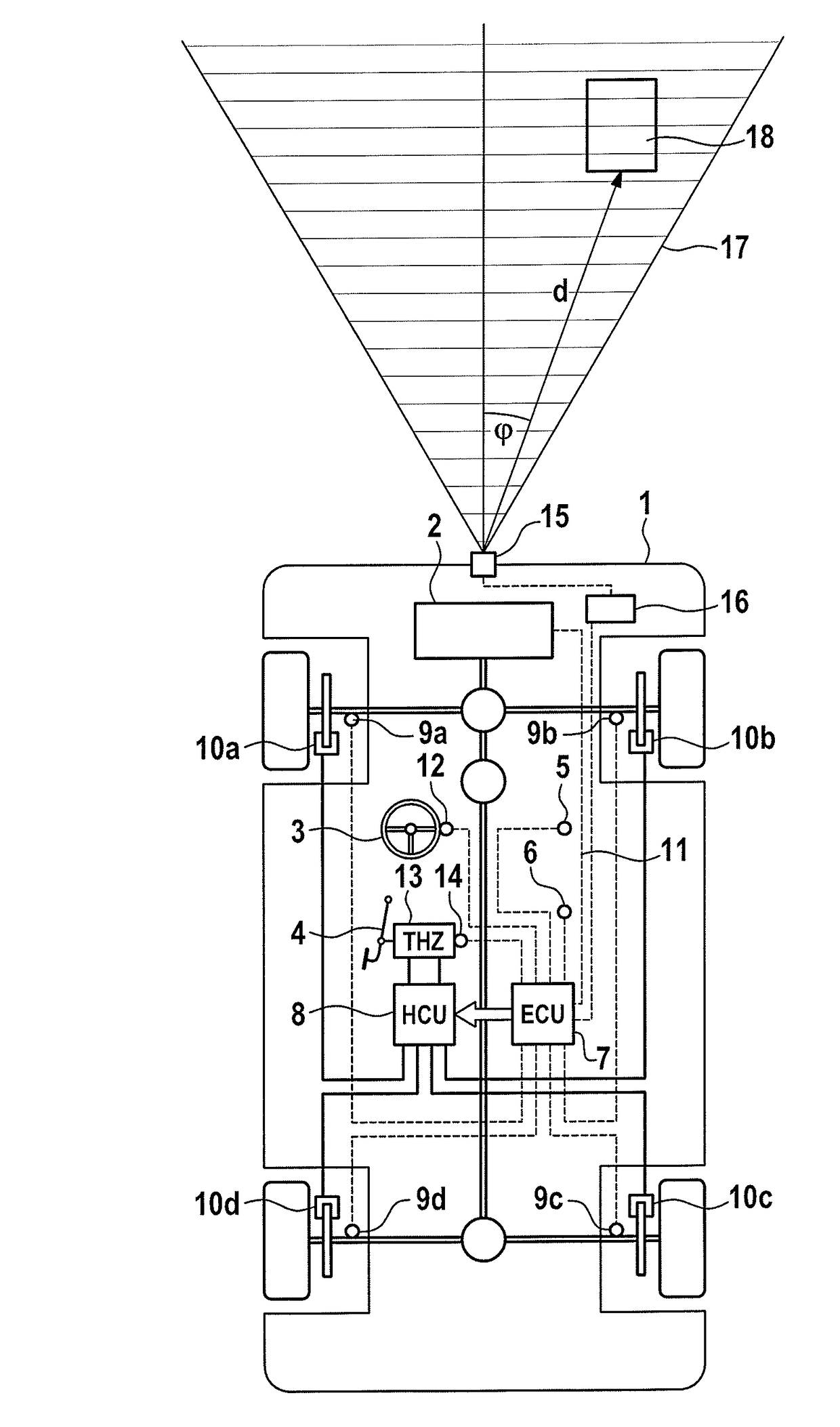
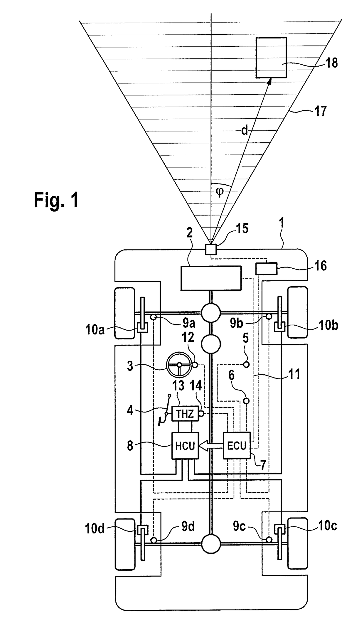
[0029]FIG. 1 shows a schematic illustration of a motor vehicle 1 which is suitable for carrying out the method according to an aspect of the invention. Said motor vehicle 1 has a drive engine 2 which drives at least some of the wheels of the vehicle, a steering wheel 3, a brake pedal 4, which is connected to a tandem master cylinder (THZ), 13, and four wheel brakes 10a-10d which can be activated individually. The method according to an aspect of the invention can be carried out even if only some of the vehicle wheels are driven. In addition to or as an alternative to hydraulic friction brakes it is also possible to use friction brakes which can be actuated electro mechanically on one, several or all of the wheels as wheel brakes. According to one alternative embodiment of the invention, the vehicle has an electric drive, and the braking torque at at least one wheel is generated at least partially by the electric machine or machines operated as a generator.

[0030]For the sensing of ve...


PUM


Abstract

A method in which the driving behavior of a vehicle is influenced depending on surroundings data in order to support an evasive maneuver as soon as a risk of collision is detected using the data from surroundings sensors and vehicle sensors. The vehicle has an electronically regulated braking system which allows a driver-independent build-up and a modulation of the braking forces on the individual wheels of the vehicle, and a steering input by the drive is supported in the event of a detected risk of collision by a driver-independent braking intervention. A brake slip of at least one wheel of the vehicle is limited to a first slip threshold in a first phase of the evasive maneuver and to a second slip threshold in a second phase of the evasive maneuver, wherein the first slip threshold is smaller than the second slip threshold. The invention further relates to an electronic controller.

Description

CROSS REFERENCE TO RELATED APPLICATIONS[0001]This application is the U.S. National Phase Application of PCT International Application No. PCT / EP2014 / 067152, filed Aug. 11, 2014, which claims priority to German Patent Application No. 10 2013 225 970.0, filed Dec. 13, 2013, the contents of such applications being incorporated by reference herein.FIELD OF THE INVENTION[0002]The invention relates to a method and to an electronic control device for regulating driving stability.BACKGROUND OF THE INVENTION[0003]In addition to electronically controlled brake systems which make available functions such as a traction controller (ABS) which prevents the wheels from locking during full braking, and a vehicle movement dynamics controller (ESC) which acts in a stabilizing fashion on the motor vehicle during dynamic driving maneuvers by means of targeted braking interventions, motor vehicles increasingly have an ambient sensor system with which other road users and non-movable obstacles can be det...

Claims


Application Information

Patent Timeline
Patent Type & Authority Patents(United States)
IPC IPC(8): B60T8/1755B60T8/24
CPCB60T8/17558B60T8/246B60T2270/30B60T2220/03B60T2250/03B60T2201/022B60T8/171B60W10/18B60W30/08B60W2420/42B60W2420/52B60W2520/14B60W2520/28B60W2540/18
Inventor BRETZIGHEIMER, KAISEURER, FRANK
Owner CONTINENTAL TEVES AG & CO OHG
Learn More