Current mirror circuit and receiver using the same
a mirror circuit and receiver technology, applied in the direction of amplifiers, amplifiers with impedence circuits, instruments, etc., can solve the problem of limited input current range, achieve high accuracy of amplifying current, prevent an increase in chip area, and wide input current range
- Summary
- Abstract
- Description
- Claims
- Application Information
AI Technical Summary
Benefits of technology
Problems solved by technology
Method used
Image
Examples
Embodiment Construction
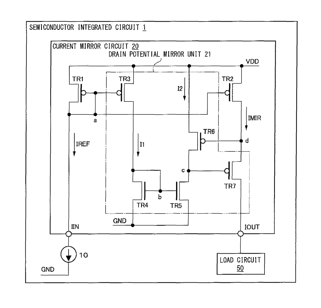
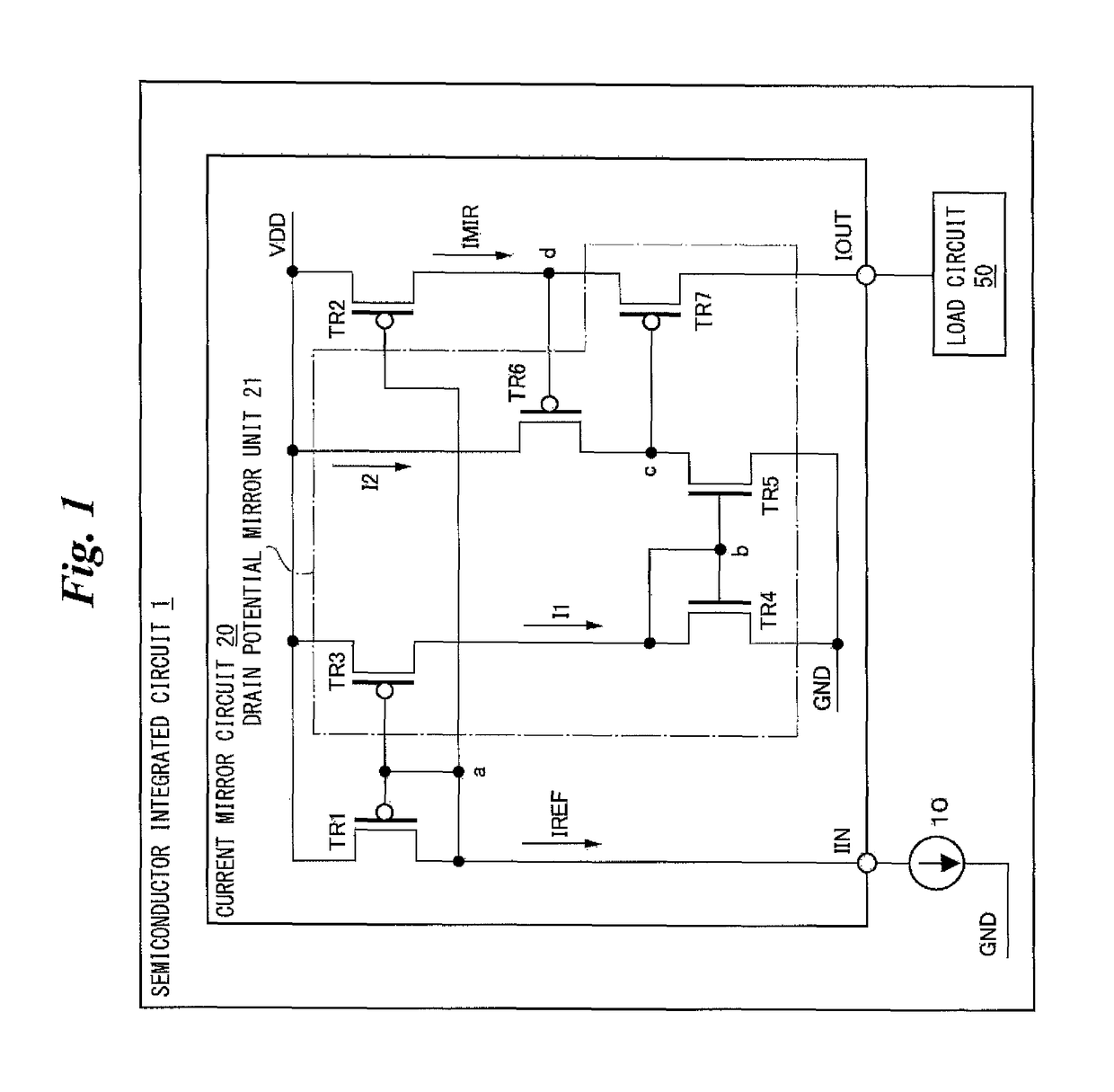
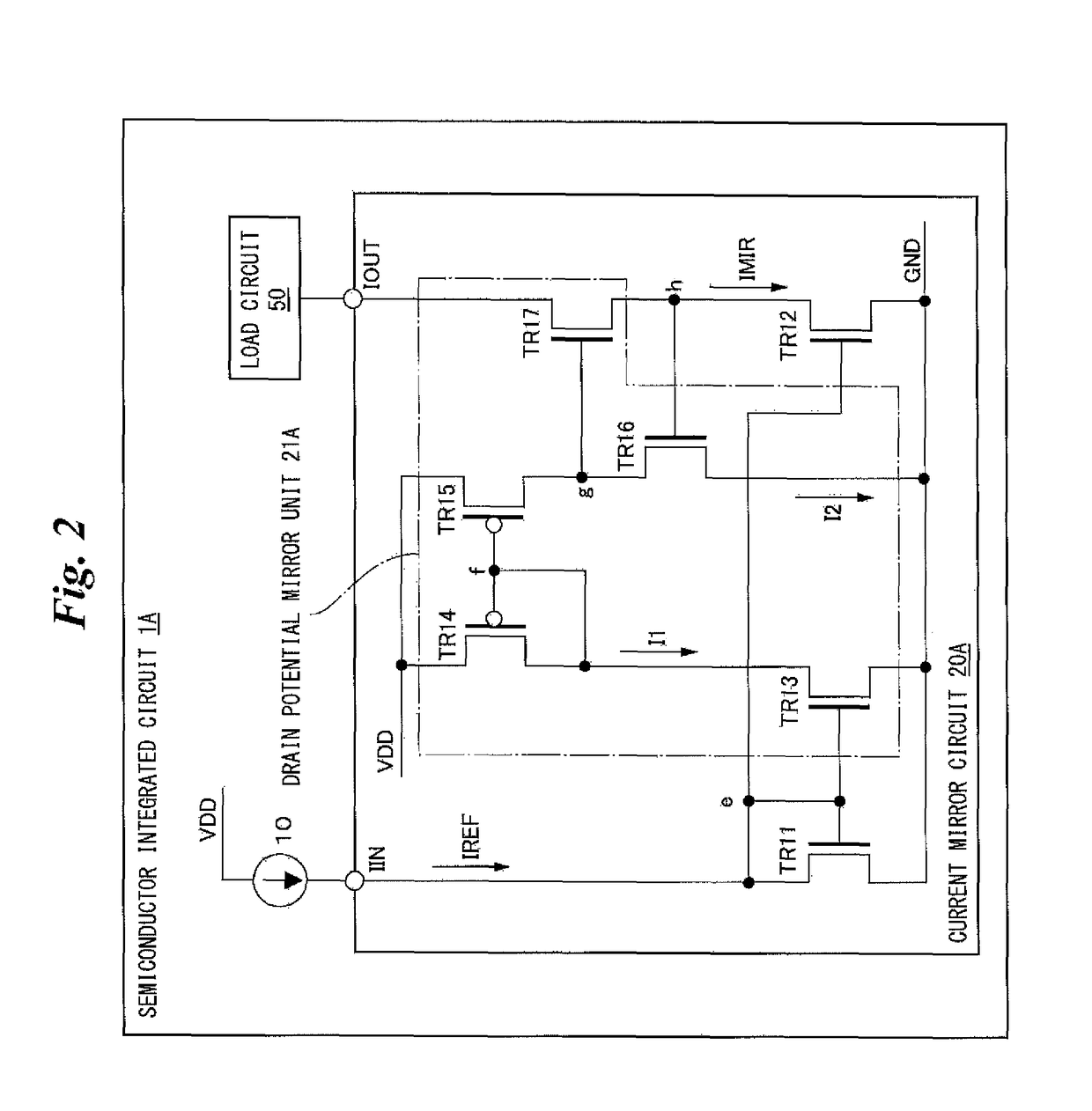
[0046]Hereinafter, embodiments of the present invention will be described with reference to the drawings. In embodiments of the invention, numerous specific details are set forth in order to provide a more thorough understanding of the invention. However, it will be apparent to one of ordinary skill in the art that the invention may be practiced without these specific details. In other instances, well-known features have not been described in detail to avoid obscuring the invention. FIG. 1 is a diagram showing an example of a semiconductor integrated circuit (IC) according to one or more embodiments of the present invention. As shown in FIG. 1, a semiconductor IC 1 may comprise a current source 10, a current mirror circuit 20, and a load circuit 50.
[0047]The current source 10 may be, for example, a MOS transistor that generates a reference current IREF in the current mirror circuit 20. The current source 10 may be connected to the drain of a transistor TR1 and the gates of transisto...
PUM
 Abstract
Description
Claims
Application Information
 - R&D
- Intellectual Property
- Life Sciences
- Materials
- Tech Scout
- Unparalleled Data Quality
- Higher Quality Content
- 60% Fewer Hallucinations
Browse by: Latest US Patents, China's latest patents, Technical Efficacy Thesaurus, Application Domain, Technology Topic, Popular Technical Reports.
© 2025 PatSnap. All rights reserved.Legal|Privacy policy|Modern Slavery Act Transparency Statement|Sitemap|About US| Contact US: help@patsnap.com


