
Cognitive reconfigurable RF technology

a reconfigurable rf and rf technology technology, applied in the direction of electrical equipment, wireless communication, transmission, etc., can solve the problems of sdr and cr not being widely adopted, upcoming wireless technologies only going to increase dependency, etc., and achieve the effect of selectivity

Active Publication Date: 2017-11-21
VIRGINIA TECH INTPROP INC
View PDF8 Cites 2 Cited by
  • Summary
  • Abstract
  • Description
  • Claims
  • Application Information

AI Technical Summary

Benefits of technology

This approach enables the creation of robust, flexible wireless devices that can operate effectively even with inherent and strong non-linearity distortions, reducing the need for highly selective filters and improving the opportunity detection probability of cognitive radios, thereby enhancing the performance of wireless systems in dynamic spectrum-sharing scenarios.

Problems solved by technology

Upcoming wireless technologies are only going to increase the dependency.
However, various engineering challenges need to be tackled before this opportunity could be exploited.
Nevertheless, SDR and CR are not widely adopted because of the difficulties involved in the design of their analog section of the hardware.
Unlike the digital section, the analog section of wireless devices cannot easily become flexible.
To be flexible without sacrificing its key performance measures such as selectivity, the RF front-end typically has to be physically large and complex.
This is one of the main reasons why SDR and CR have not been widely implemented in mobile handsets.
However, the pre-selector filter is the part of the RF front-end which is least yielding for flexibility.
Often, flexible pre-selector filters are either too big or very poorly selective.

Method used


Image

  • Cognitive reconfigurable RF technology
  • Cognitive reconfigurable RF technology
  • Cognitive reconfigurable RF technology

Examples


Embodiment Construction

[0032]Detailed embodiments of the present invention are disclosed herein; however, it is to be understood that the disclosed embodiments are merely exemplary of the invention, which may be embodied in various forms. Therefore, specific structural and functional details disclosed herein are not to be interpreted as limiting, but merely as a representative basis for teaching one skilled in the art to variously employ the present invention in virtually any appropriately detailed method, structure or system. Further, the terms and phrases used herein are not intended to be limiting, but rather to provide an understandable description of the invention.

[0033]There are various types of tunable RF filter technologies. Generally, tunable filters can be categorized as, mechanically tunable, magnetically tunable and electronically tunable filters. Mechanically tunable filters change their characteristics by changing their physical structure. The bulkiness and slow tuning speed of mechanically ...


PUM


Abstract

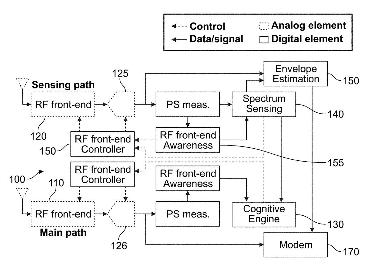
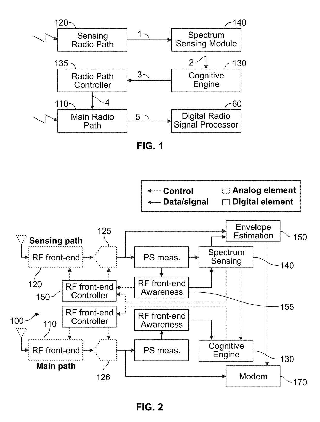
The present invention provides a radio architecture that contains a main radio path and a sensing path. The parameters of the main radio path are controlled by a cognitive engine. The main radio path is tuned to a desired frequency band. The sensing path is used to monitor the spectrum around the desired frequency band. To minimize effects of undesired non-linearity on sensing, sensing path may have a lower gain setting. The cognitive engine determines the optimal setting of the main RF front-end with respect to the current state of the spectrum.

Description

RELATED APPLICATIONS[0001]This application claims the benefit of U.S. Provisional Application No. 62 / 041,268 filed Aug. 25, 2014 and herein incorporated by reference.STATEMENT REGARDING FEDERALLY SPONSORED RESEARCH & DEVELOPMENT[0002]Not applicable.INCORPORATION BY REFERENCE OF MATERIAL SUBMITTED ON A COMPACT DISC[0003]Not applicable.BACKGROUND OF THE INVENTION[0004]There is an increasingly dependence on wireless devices. Upcoming wireless technologies are only going to increase the dependency. In the coming years, not only will cell-phones and laptops be wireless, but also cars, houses, appliances such as coffee machines, and even our body organs and almost anything may be wireless enabled. The Internet of everything (IoE) is gasping to seamlessly network us with the physical world.[0005]The expansion of wireless use is expected to fundamentally change the way we live, work and play. However, various engineering challenges need to be tackled before this opportunity could be exploit...

Claims


Application Information

Patent Timeline
Patent Type & Authority Patents(United States)
IPC IPC(8): H04W24/02H04B1/00H04W72/54
CPCH04B1/001
Inventor IMANA, EYOSIAS YOSEPHYANG, TAE YOUNGREED, JEFFREY H.
Owner VIRGINIA TECH INTPROP INC
Learn More