System and method for regulation of multi-level boost based rectifiers with power factor correction

a technology of boost-based rectifiers and power factor correction, which is applied in the direction of energy industry, efficient power electronics conversion, electric variable regulation, etc., can solve the problems of preventing the use of weight and volume sensitive applications of overall systems, affecting the cost of overall systems, and non-negligible core losses, so as to reduce the maximum voltage swing value of boost inductors, and reduce the volume and losses of boost inductors

Inactive Publication Date: 2017-11-14
IDT EURO GMBH
View PDF7 Cites 6 Cited by
  • Summary
  • Abstract
  • Description
  • Claims
  • Application Information

AI Technical Summary

Benefits of technology

[0007]In accordance with a first broad aspect, there is provided a system for regulating operation of a non-symmetric boost based front end stage of a rectifier with power factor correction, the system comprising an active capacitive divider coupled to an inductor of the front end stage for reducing a maximum voltage swing value of the inductor.
[0008]In accordance with a second broad aspect, there is provided a method for regulating operation of a non-symmetric boost based front end stage of a rectifier with power factor correction, the method comprising reducing a maximum voltage swing value of an inductor of the front end stage using an active capacitive divider.
[0009]In accordance with a second broad aspect, there is provided a method for reducing a volume and losses of a boost inductor in a PFC rectifier, the method comprising providing a biasing circuit and an auxiliary winding for providing a low frequency biasing current, thereby cancelling a flux component of the inductor at twice line frequency.
[0010]In accordance with a second broad aspect, there is provided a system for reducing a volume and losses of a boost inductor in a PFC rectifier, the system comprising an auxiliary winding coupled to the inductor and a biasing circuit coupled to the auxiliary winding for providing a low frequency biasing current, thereby cancelling a flux component of the inductor at twice line frequency.

Problems solved by technology

One of the major drawbacks of boost-based power factor correction (PF) rectifiers is their bulky and heavy inductor significantly affecting the cost of overall system and preventing its use in weight and volume sensitive applications.
The large boost inductor also causes non-negligible core losses and results in a relatively large parasitic capacitance of the winding.
Another problem of the conventional boost-based topologies is switching tosses, causing heat dissipation problems whose handling often requires bulky and costly cooling components.
The switching losses are mostly related to the operation of the semiconductor switches at relatively high switching voltages.
Moreover, one of the main drawbacks of PFC rectifiers for boost converters operating in continuous conduction mode (CCM) is the bulky boot inductor, which is one of the main contributors to the overall weight, volume, and cost of the entire system.
However, these methods have limitations.

Method used


Image

  • System and method for regulation of multi-level boost based rectifiers with power factor correction
  • System and method for regulation of multi-level boost based rectifiers with power factor correction
  • System and method for regulation of multi-level boost based rectifiers with power factor correction

Examples


Embodiment Construction

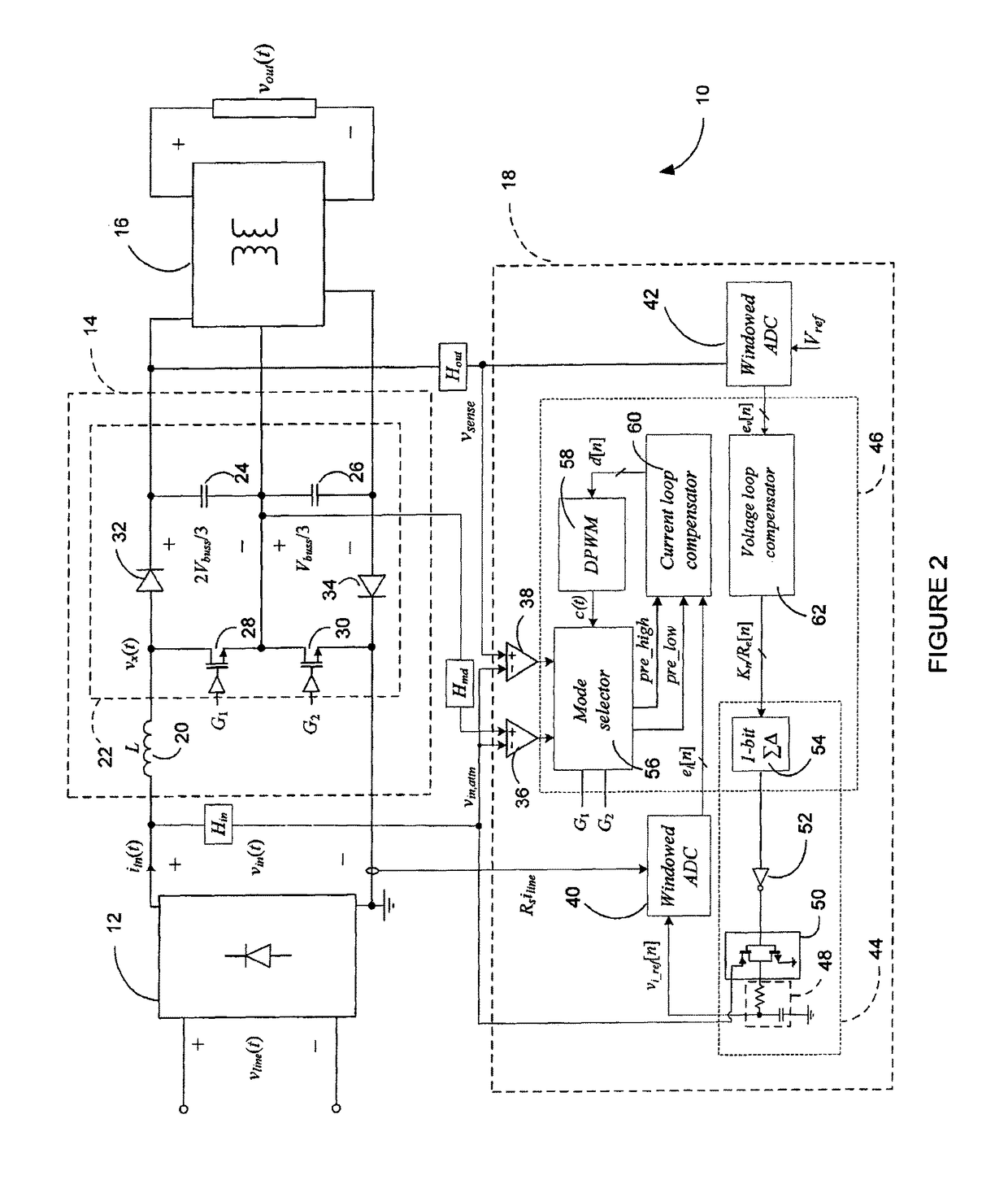
[0040]Referring to FIG. 1, a power factor correction (PFC) rectifier 10 according to a first embodiment will now be described. The PFC rectifier 10 is based on the non-symmetric multi-level boost (NSMB) converter topology and illustratively comprises a full-wave diode rectifier 12, a non-symmetric multi-level boost front-end stage 14, a charge-balancing isolated downstream DC-DC stage 16, and a controller 18. The full-wave diode rectifier 12 may be used to rectify an input line voltage vline(t), thereby producing a voltage vin(t). The non-symmetric multi-level boost front-end stage 14 and the controller 18 are then used to force an input current iin(t) to follow the waveform of vin(t) and produce a regulated bus voltage Vbuss(t). As the bus voltage typically has a high value and cannot be directly used the charge-balancing isolated downstream DC-DC stage 16 is further used to reduce the bus voltage to a lower value. Using the charge-balancing isolated downstream DC-DC stage 16, dire...


PUM


Abstract

A control method and system are provided for regulating operation of power factor correction rectifiers based on the non-symmetric boost converter topology. Control of both the front-end stage is enabled taking sinusoidal current from the utility network and a downstream converter providing isolated DC output voltage. Also provided are a method and system for reducing volume of reactive components in boost-based rectifiers with power factor correction. Flux density through the inductor is reduced with a biasing inductor current having a much lower frequency than the switching frequency of the converter.

Description

CROSS-REFERENCE TO RELATED APPLICATIONS[0001]This application is a national stage filing under section 371 of International Application No. PCT / EP2014 / 058117, filed on Apr. 22, 2014, and published in English on Oct. 23, 2014, as WO 2014 / 170501 A2 and claims priority of U.S. Provisional application 61 / 813,951 filed on Apr. 19, 2013, the entire disclosure of these applications being hereby incorporated herein by reference.TECHNICAL FIELD[0002]The present invention relates to regulation of multi-level boost-based power factor correction rectifiers.BACKGROUND OF THE ART[0003]One of the major drawbacks of boost-based power factor correction (PF) rectifiers is their bulky and heavy inductor significantly affecting the cost of overall system and preventing its use in weight and volume sensitive applications. The large boost inductor also causes non-negligible core losses and results in a relatively large parasitic capacitance of the winding. This capacitance allows high frequency current t...

Claims


Application Information

Patent Timeline
Patent Type & Authority Patents(United States)
IPC IPC(8): H02M7/15H02M1/12H02M1/42H02M7/04H02M3/158
CPCH02M7/04H02M1/12H02M1/4225Y02P80/112H02M3/158Y02B70/126Y02B70/10Y02P80/10H02M1/0085
Inventor MAHDAVIKHAH, BEHZADPRODIC, ALEKSANDAR
Owner IDT EURO GMBH
Why Eureka
Try Eureka