Method for manufacturing a thin film structural system

a manufacturing method and thin film technology, applied in the field of manufacturing a thin film structure and a large-scale thin film structural system, can solve the problems of increasing the thickness of the material, increasing the packaging space, and increasing the weight penalty, so as to facilitate packaging and the deployment of the expandable space structure, the effect of preventing progressive damag

Active Publication Date: 2017-11-14
NASA
View PDF26 Cites 1 Cited by
  • Summary
  • Abstract
  • Description
  • Claims
  • Application Information

AI Technical Summary

Benefits of technology

[0008]The thin film structural system may be configured as a space structure, which may be an expandable space structure. The space structure may include one or more thin film structures where the predefined pattern of one or more of the reinforcing elements provides a local stiffening feature and / or a hinge, a hinge line and / or a folding line to facilitate packaging and deployment of the expandable space structure. The predefined pattern may be configured to redistribute loads around a damaged portion of the membrane and / or the thin film structure, to prevent progressive damage.

Problems solved by technology

Spanning large areas with thin film materials, e.g., membrane structures, to separate environments or to collect and / or reflect spatially disperse particles such as chemicals or electromagnetic radiation can result in progressive failure due to tearing or ripping of the membrane.
Increasing the material thickness introduces a weight penalty and increases packaging space, both disadvantages for a space application.
Adding “rip stop” to the membrane typically requires bonding a reinforcing material to the membrane using an adhesive, using human touch labor and wet and / or dry bonding, which can be very expensive and often damaging to the substrate.

Method used


Image

  • Method for manufacturing a thin film structural system
  • Method for manufacturing a thin film structural system
  • Method for manufacturing a thin film structural system

Examples


Embodiment Construction

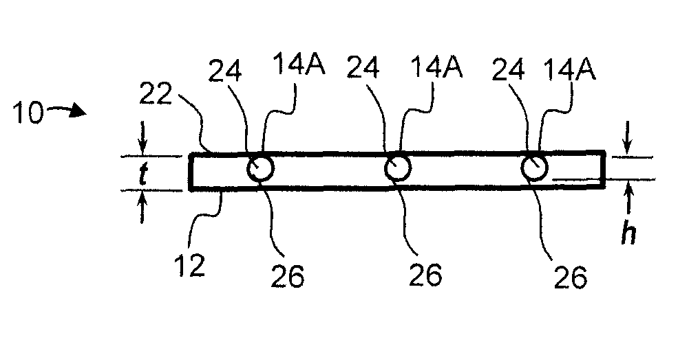
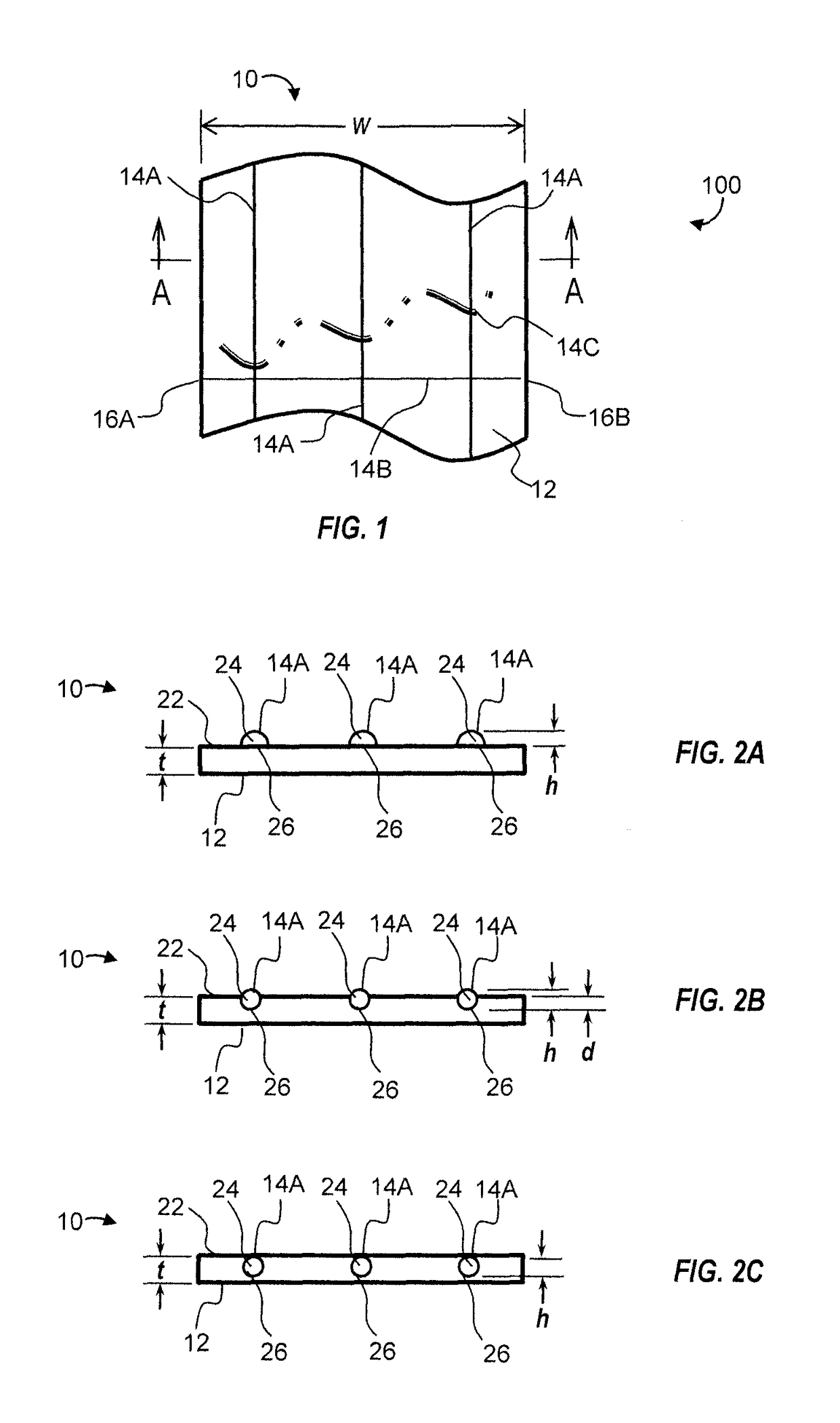
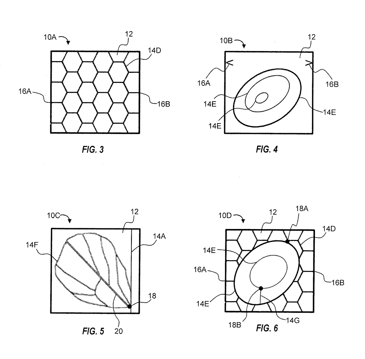
[0019]Referring to the drawings wherein like reference numbers represent like components throughout the several figures, the elements shown in FIGS. 1-7 are not necessarily to scale or proportion. Accordingly, the particular dimensions and applications provided in the drawings presented herein are not to be considered limiting. A method of manufacturing a low mass, large-scale hierarchical thin film structural system is provided herein. FIG. 1 shows an example of a thin film structure 10 which may be incorporated in a structural system 100. In one embodiment, the structural system 100 may be a space structure, wherein a thin film structure such as the structure 10 may provide a lightweight, damage tolerant, flexible and deployable structure. As used herein, the term “thin” can refer to a structure having a thickness of about 0.5 microns to 250 microns. The structural system 100 may be, for example, an expandable system, and / or may be a system used for space exploration, such as a so...


PUM

PropertyMeasurementUnit
thicknessaaaaaaaaaa
widthaaaaaaaaaa
widthaaaaaaaaaa

Abstract

A method for manufacturing a thin film structural system including a thin film structure includes depositing a reinforcing material in a liquid form in a predefined pattern on a thin film membrane, and transforming the reinforcing material in the predefined pattern to form a reinforcing element connected to the thin film membrane. The reinforcing material may be deposited in a melted form and solidified by cooling, may be transformed by a light or laser induced chemical reaction, or may be deposited and solidified such that the reinforcing element is at least partially embedded in the thin film membrane. The predefined pattern may redistribute loads around a damaged portion of the thin film structure, or define a hinge, a folding line, a stiffening feature. The reinforcing element may be electrically, optically or thermally conductive, to communicate with a device included in the system. The system may be a space structure.

Description

CROSS-REFERENCE TO RELATED APPLICATIONS[0001]This application claims the benefit of and priority to U.S. Provisional Patent Application No. 61 / 431,245, filed Jan. 10, 2011, which is hereby incorporated by reference in its entirety.STATEMENT REGARDING FEDERALLY SPONSORED RESEARCH OR DEVELOPMENT[0002]The invention described herein was made in part by employees of the United States Government and may be manufactured and used by or for the Government of the United States of America for governmental purposes without the payment of any royalties thereon or therefor.TECHNICAL FIELD[0003]This disclosure relates to manufacturing of a thin film structure and a low mass, large-scale thin film structural system including a thin film structure.BACKGROUND OF THE INVENTION[0004]Lightweight, damage-tolerant, flexible and deployable thin film structures are enabling for a variety of space exploration missions when configured, for example, as solar sails, solar arrays, sunshields, radar and reflect a...

Claims


Application Information

Patent Timeline
Patent Type & Authority Patents(United States)
IPC IPC(8): B29C70/74B32B27/28B32B5/18B32B37/14
CPCB32B37/142B29C70/747B32B5/18B32B27/281B32B2307/10Y10T428/31721B32B2307/40B32B2310/0806Y10T156/10Y10T428/24802Y10T428/31504B32B2307/302
Inventor BELVIN, WENDELL KEITHSLEIGHT, DAVID W.CONNELL, JOHN W.BURNS, THOMAS J.HOLLOWAY, NANCY M. H.PALMIERI, FRANK L.WAINWRIGHT, GARY A.ANDREWS, ROBERT C.ZANDER, MARTIN ECKHARD
Owner NASA
Why Eureka
Try Eureka