
Apparatus and method for power supply

a power supply and power supply technology, applied in emergency power supply arrangements, instruments, liquid/fluent solid measurements, etc., can solve the problems of less preferable energy saving performance, lower power conversion efficiency of the main power circuit, and increased power consumption of the apparatus for power supply in general, so as to improve the power conversion efficiency of the power supply apparatus in general.

Active Publication Date: 2017-11-07
SPI ELECTRONICS
View PDF8 Cites 5 Cited by
  • Summary
  • Abstract
  • Description
  • Claims
  • Application Information

AI Technical Summary

Benefits of technology

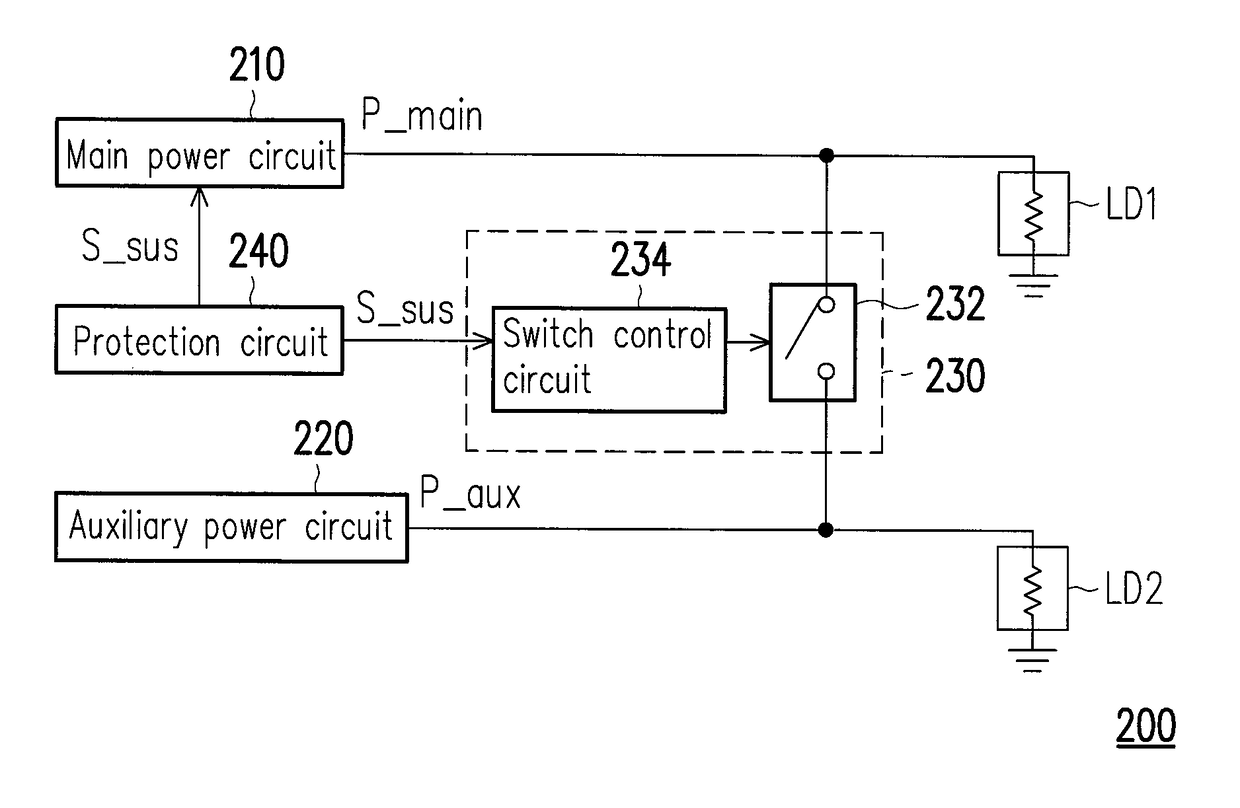
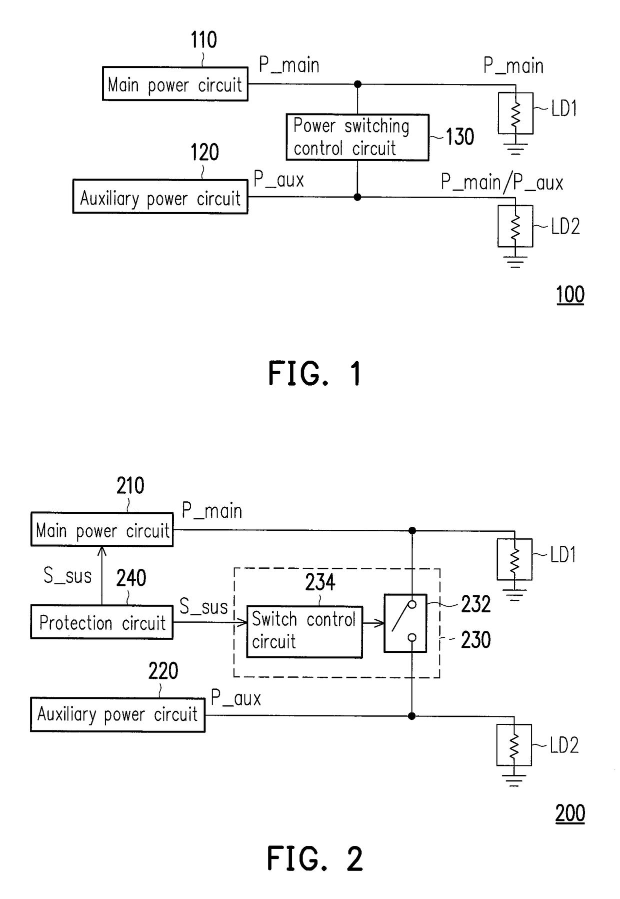
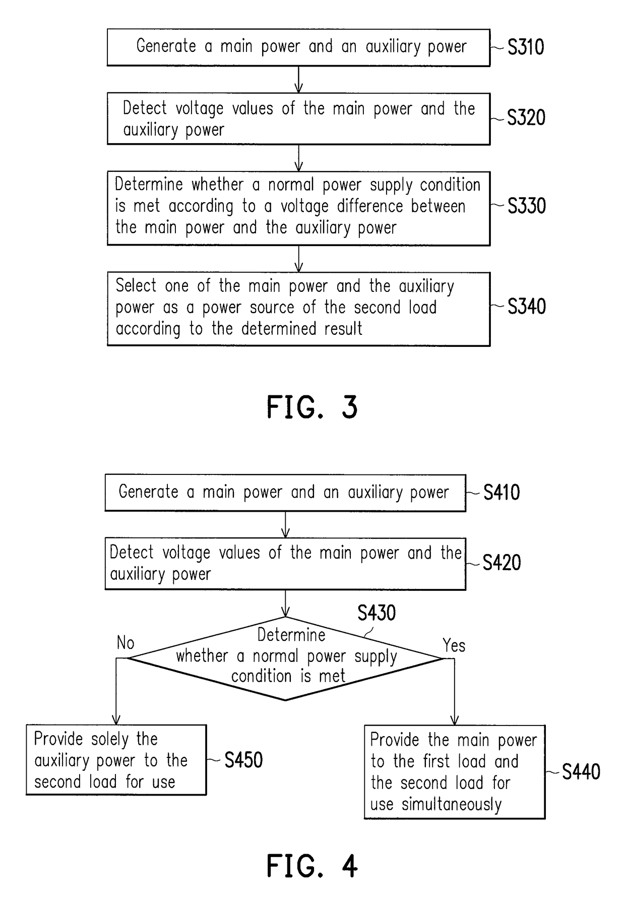
The invention provides an apparatus and method for power supply that can determine if the main power circuit is operating normally based on the voltage difference between the main power and the auxiliary power. When the main power circuit is operating normally, the power source of the auxiliary power load is switched to the main power, which improves power conversion efficiency. On the other hand, when the main power circuit is not operating normally, the power switching control circuit disconnects the electrical connection between the main power circuit and the auxiliary power circuit, preventing current generated by the auxiliary power circuit from being reversely fed back to the main power circuit and damaging the circuit.

Problems solved by technology

When electronic apparatuses are more and more commonly used, the power consumption thereof also increases accordingly.
However, due to the circuit specification and design concerning the type of typology, the power conversion efficiency of the conventional auxiliary power circuit is lower than the power conversion efficiency of the main power circuit.
Thus, the power supply apparatus may generate too much blind power and thus have a less preferable energy saving performance.

Method used


Image

  • Apparatus and method for power supply
  • Apparatus and method for power supply
  • Apparatus and method for power supply

Examples


Embodiment Construction

[0033]The embodiments of the invention provide an apparatus and a method for power supply. The apparatus for power supply is capable of determining whether a main power circuit is in a normal operation state according to a voltage difference between a main power and an auxiliary power. In addition, when the main power circuit is in the normal operation state, a power source of an auxiliary power load is switched to the main power provided by the main power circuit, so that a power conversion efficiency of the apparatus for power supply in general is improved. In order to make the invention more comprehensible, embodiments are described below as the examples to show the invention. Also, wherever possible, the same reference numbers are used in the drawings and the description to refer to the same or like parts / components / steps.

[0034]FIG. 1 is a schematic view illustrating an apparatus for power supply according to an embodiment of the invention. Referring to FIG. 1, an apparatus 100 ...


PUM


Abstract

An apparatus and a method for power supply are provided. The apparatus for power supply includes a main power circuit, an auxiliary power circuit and a power switching control circuit. The main power circuit is configured to generate a main power suitable to be provided to a first load and a second load for use. The auxiliary power circuit is configured to generate an auxiliary power suitable to be provided to the second load for use. The power switching control circuit is configured to detect a voltage difference between the main power and the auxiliary power and determine whether the apparatus meets a normal power supply condition, so as to select one of the main power and auxiliary power as a power source of the second load.

Description

CROSS-REFERENCE TO RELATED APPLICATION[0001]This application claims the priority benefit of Taiwan application serial no. 102147830, filed on Dec. 23, 2013. The entirety of the above-mentioned patent application is hereby incorporated by reference herein and made a part of this specification.BACKGROUND OF THE INVENTION[0002]1. Field of the Invention[0003]The invention relates to a power supply technology, and particularly relates to an apparatus for power supply under a power supply framework having a main power circuit and an auxiliary power circuit and a method for power supply thereof.[0004]2. Description of Related Art[0005]When electronic apparatuses are more and more commonly used, the power consumption thereof also increases accordingly. To reduce the power consumption of electronic apparatuses and provide effective power management, a power management mechanism referred to as the advanced configuration and power interface (ACPI) standard has been used to manage the power of ...

Claims


Application Information

Patent Timeline
Patent Type & Authority Patents(United States)
IPC IPC(8): G06F1/30H02J1/10G06F1/26H02J9/06
CPCG06F1/30G06F1/263H02J9/061H02J1/10Y10T307/344
Inventor TSAI, CHIEN-LI
Owner SPI ELECTRONICS
Learn More