Control apparatus for power transmission system

a technology of power transmission system and control apparatus, which is applied in mechanical apparatus, transportation and packaging, gearing, etc., can solve the problems of deterioration of driving ability and drivability, and achieve the effect of accurately determining whether the vehicle is

Active Publication Date: 2017-11-07
TOYOTA JIDOSHA KK
View PDF8 Cites 2 Cited by
  • Summary
  • Abstract
  • Description
  • Claims
  • Application Information

AI Technical Summary

Benefits of technology

[0007]The present disclosure provides a control apparatus for a power transmission system, which is able to prevent or reduce deterioration of drivability at the time of reducing vehicle vibration or noise.
[0009]With the above-described control apparatus, when the state of the vehicle is the predetermined state of the vehicle where a vibration of the vehicle occurs, weak circulating torque is generated to fill the backlash inside the automatic transmission and in the power transmission path by half-engaging the engagement device configured to establish the second power transmission path while the first power transmission path remains established in the automatic transmission. Thus, it is possible to reduce a vibration of the vehicle or noise resulting from the vibration of the vehicle. At this time, because the speed ratio of the second power transmission path is alternatively set to one of the lower vehicle speed-side speed ratio with respect to the speed ratio of the first power transmission path and the higher vehicle speed-side speed ratio with respect to the speed ratio of the first power transmission path in response to the traveling state. Therefore, it is possible to generate weak circulating torque in a direction to increase the input shaft rotation speed of the automatic transmission or in a direction to reduce the input shaft rotation speed of the automatic transmission (that is, to fill the backlash) in accordance with the traveling state, such as a state where the vehicle is accelerating, a state where the vehicle is decelerating and a state where the vehicle is traveling on an uphill or a downhill. Thus, at the time of reducing a vibration of the vehicle or noise, it is possible to prevent or reduce deterioration of drivability.
[0013]With the above-described control apparatus, by setting the speed ratio of the continuously variable transmission mechanism to one of the lower vehicle speed-side speed ratio and the higher vehicle speed-side speed ratio, it is possible to alternatively set, in response to the traveling state, the speed ratio of the second power transmission path to one of the lower vehicle speed-side speed ratio with respect to the speed ratio of the first power transmission path and the higher vehicle speed-side speed ratio with respect to the speed ratio of the first power transmission path. At this time, because the speed ratio of the second power transmission path is allowed to be steplessly adjusted, it is possible to exert inertia suitable for the state of the vehicle. That is, it is possible to generate weak circulating torque commensurate with the traveling state. That is, it is possible to cause a weak tie-up state without intricately adjusting engaging force for half-engaging the engagement device for establishing the second power transmission path.
[0015]With the above-described control apparatus, by setting the speed stage that is established in the second power transmission path to one of the lower vehicle speed-side speed stage and the higher vehicle speed-side speed stage with respect to the currently established speed stage, it is possible to easily alternatively set in response to the traveling state the speed ratio of the second power transmission path to one of the lower vehicle speed-side speed ratio with respect to the speed ratio of the first power transmission path and the higher vehicle speed-side speed ratio with respect to the speed ratio of the first power transmission path.
[0019]With the above-described control apparatus, it is possible to accurately determine whether the vehicle is in the vibration generating state, so it is possible to appropriately determine the state of the vehicle where a vibration of the vehicle is occurring or noise resulting from the vibration of the vehicle is occurring.

Problems solved by technology

In this case, drivability may deteriorate because load acts in a direction to reduce the input shaft rotation speed of the automatic transmission, that is, because torque internally circulates.
That is, if the semi-interlock state is uniformly established in order to reduce vehicle vibration or noise, drivability may be deteriorated.

Method used


Image

  • Control apparatus for power transmission system
  • Control apparatus for power transmission system
  • Control apparatus for power transmission system

Examples


first embodiment

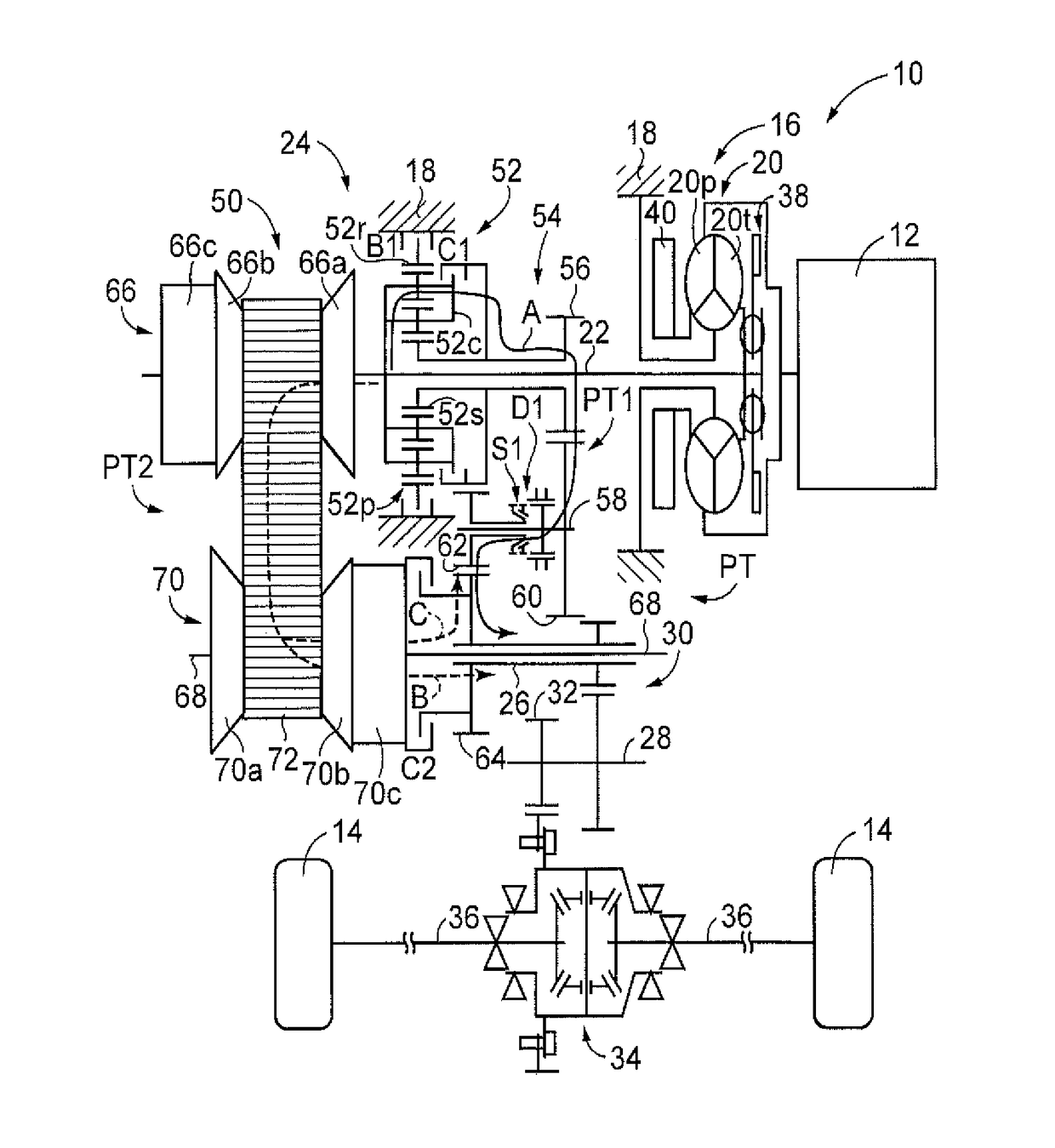
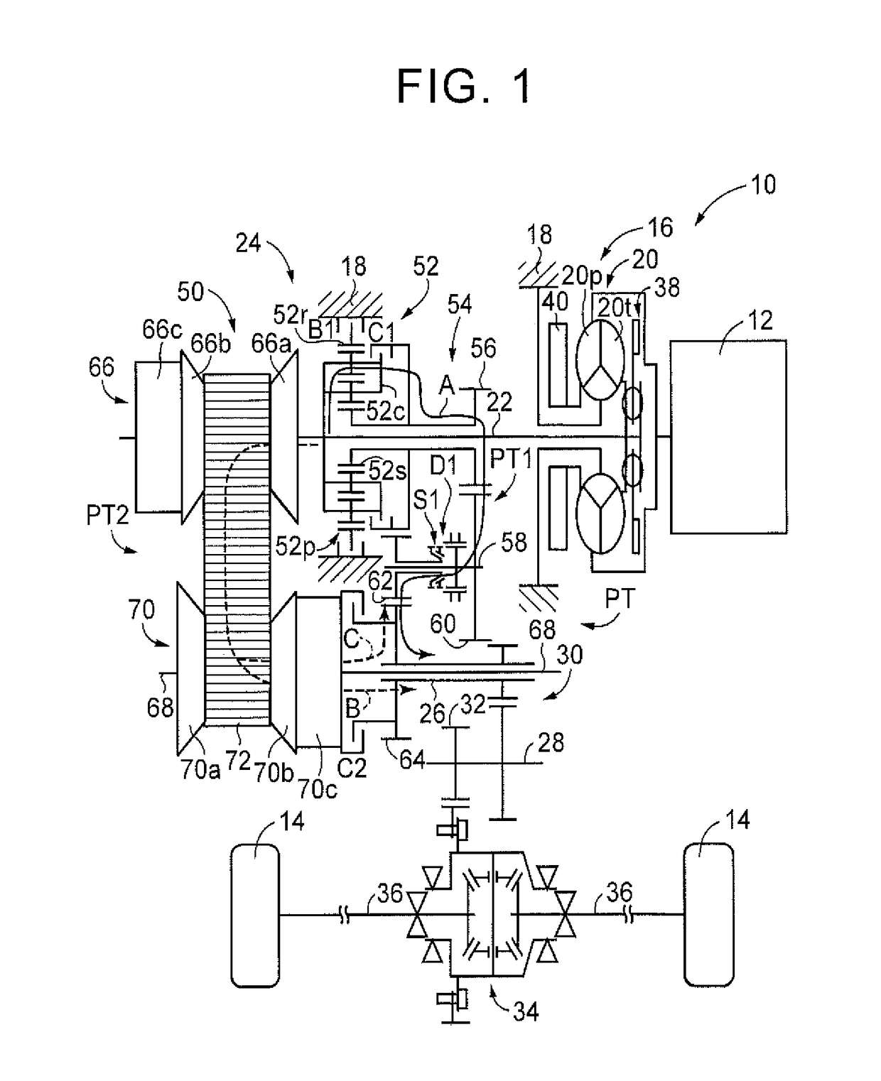
[0030]FIG. 1 is a view that illustrates the schematic configuration of a vehicle 10 to which the present disclosure is applied. In FIG. 1, the vehicle 10 includes an engine 12, drive wheels 14, and a power transmission system 16. The engine 12 is a gasoline engine, a diesel engine, or the like, that functions as a driving force source for propelling the vehicle 10. The power transmission system 16 is provided in a power transmission path between the engine 12 and the drive wheels 14. The power transmission system 16 includes a torque converter 20, an input shaft 22, an automatic transmission 24, an output shaft 26, a counter shaft 28, a reduction gear unit 30, a differential gear set 34, a pair of axles 36, and the like. The input shaft 22 is coupled to the torque converter 20. The automatic transmission 24 is coupled to the input shaft 22. The output shaft 26 is coupled to the output side of the automatic transmission 24. The pair of axles 36 are coupled to the differential gear se...

second embodiment

[0094]As described above, according to the present second embodiment, by setting the speed stage for establishing the second power transmission path PT2 to the lower vehicle speed-side speed stage or the higher vehicle speed-side speed stage with respect to the currently established speed stage, it is possible to easily alternatively set in response to the traveling state the speed ratio γpt2 of the second power transmission path PT2 to the lower vehicle speed-side speed ratio with respect to the speed ratio of the first power transmission path PT1 or the higher vehicle speed-side speed ratio with respect to the speed ratio of the first power transmission path PT1.

[0095]The first and second embodiments of the present disclosure are described in detail with reference to the accompanying drawings; however, the present disclosure is also applicable to other embodiments.

[0096]For example, in the above-described first and second embodiments, when torque is circulated from the other power...


PUM


Abstract

When a state of a vehicle is a predetermined state of the vehicle where vehicle vibration occurs, weak circulating torque is generated to fill backlash inside an automatic transmission and in a power transmission path by half-engaging a second clutch for establishing a second power transmission path while a first power transmission path remains established in the automatic transmission. A speed ratio of the second power transmission path is alternatively set to a lower vehicle speed-side speed ratio with respect to a speed ratio of the first power transmission path or a higher vehicle speed-side speed ratio with respect to the speed ratio of the first power transmission path in response to a traveling state. It is possible to generate weak circulating torque in a direction to increase an input shaft rotation speed or in a direction to reduce the input shaft rotation speed in accordance with the traveling state.

Description

INCORPORATION BY REFERENCE[0001]The disclosure of Japanese Patent Application No. 2015-157742 filed on Aug. 7, 2015 including the specification, drawings and abstract is incorporated herein by reference in its entirety.BACKGROUND[0002]1. Technical Field[0003]The present disclosure relates to a control apparatus for a power transmission system including an automatic transmission that is able to provide different power transmission paths that transmit power of a driving force source to a drive wheel.[0004]2. Description of Related Art[0005]There is well known a control apparatus for a power transmission system including an automatic transmission in which one of a first power transmission path and a second power transmission path, which transmits power of a driving force source to a drive wheel, is selectively established. In a predetermined state of a vehicle where vehicle vibration occurs, the control apparatus reduces the vehicle vibration or noise resulting from the vehicle vibrati...

Claims


Application Information

Patent Timeline
Patent Type & Authority Patents(United States)
IPC IPC(8): B60W30/20F16H61/70F16H37/02F16H61/662F16H61/02
CPCF16H61/702B60W30/20F16H37/021F16H37/022F16H61/662F16H61/66259F16H61/0204F16H2702/06B60Y2300/20F16H2702/02F16H59/16F16H59/68F16H61/0206F16H61/0213F16H61/688F16H2037/026F16H3/663F16H57/0006F16H2200/0052F16H2200/2007F16H2200/2043F16H2200/2066F16H2200/2082F16H2057/0012
Inventor NAKAMURA, KAZUAKI
Owner TOYOTA JIDOSHA KK
Why Eureka
Try Eureka