
Capped bearing with vibration sensor

a technology of vibration sensor and bearing, which is applied in the direction of roller bearings, rigid supports of bearing units, mechanical apparatus, etc., can solve the problems of reducing signal-to-noise ratio, introducing attenuation, and good vibration transmission, and achieves good sensitivity and signal-to-noise ratio, low cost, and high quantity

Active Publication Date: 2017-10-24
AB SKF
View PDF23 Cites 1 Cited by
  • Summary
  • Abstract
  • Description
  • Claims
  • Application Information

AI Technical Summary

Benefits of technology

The invention provides a vibration sensor solution for bearings that is highly efficient, cost-effective, and fully integrated. The sensor is attached to the bearing by a material bonded connection, which ensures a good transmission of vibrations and stiffens the cap. The cap has at least one radial end face in direct contact to the bearing ring, reducing the attenuation of vibrations and impacting the cap's eigenmode vibrations. The cap can be retrofitted and includes an encapsulation for damping and protecting the sensor. The sensor solution remains compact and highly durable. It can provide an air-filled chamber accommodating the sensor and is manageable in terms of resonances.

Problems solved by technology

Attaching the sensor to the cap rather than directly to one of the bearing rings inevitably introduces attenuation and reduces the signal-to-noise-ratio such that this is a highly non-obvious choice for the sensor location.
This rigid connection leads to a good transmission of vibrations and stiffens the cap.

Method used


Image

  • Capped bearing with vibration sensor
  • Capped bearing with vibration sensor
  • Capped bearing with vibration sensor

Examples


Embodiment Construction

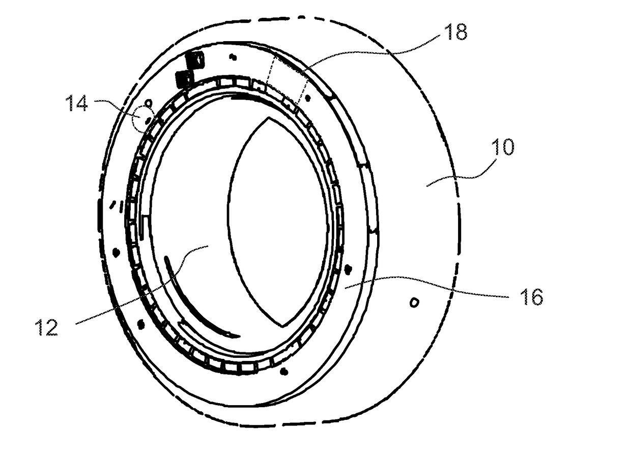
[0026]FIG. 1 is a schematic perspective view of a bearing according to the invention. The outer dimensions are those of any ISO standard bearing. The bearing is a capped bearing and includes an outer ring as a first ring 10, an inner ring as a second ring 12, at least one row of rolling elements 14 arranged in a rolling chamber between the first ring 10 and the second ring 12 and a cap 16 formed as a stamped sheet metal piece attached to the first ring 16 so as to close the rolling chamber.

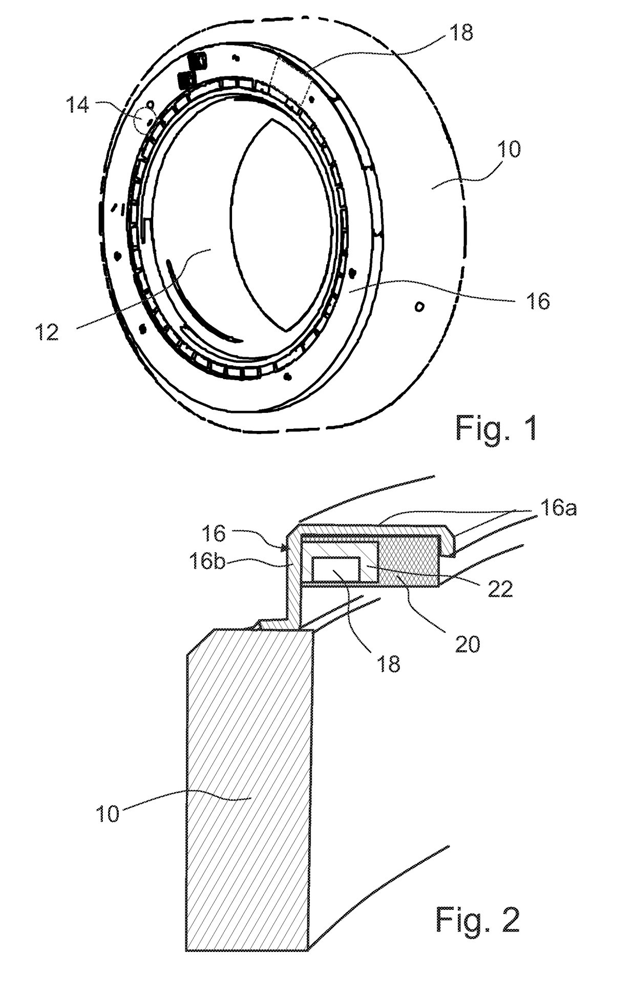
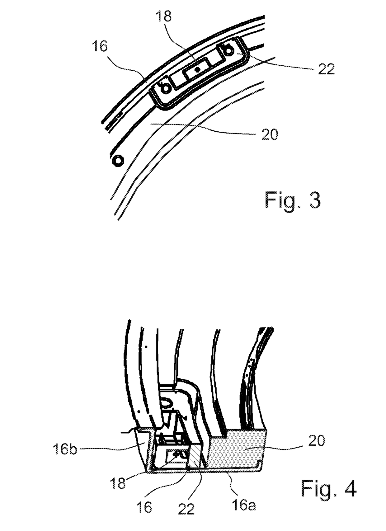
[0027]FIG. 2 is a sectional view of the first ring 10 with the cap 16 attached. A vibration sensor 18 is attached on the inside surface of the cap 16. Further, a data processing unit for processing the sensor data and a wireless transmission unit or other kind of communication interface may be provided in an electronics package attached to the same inside surface of the cap 16 (not shown).

[0028]The cap 16 has a flange via which it is attached to the first ring 10 by brazing. This rigid connection ...


PUM

PropertyMeasurementUnit
dimensionsaaaaaaaaaa
signal-to-noise-ratioaaaaaaaaaa
frictionaaaaaaaaaa

Abstract

A bearing includes a first ring, a second ring, at least one row of rolling elements arranged in a rolling chamber disposed between the first ring and the second ring, and a cap attached to the first ring that is configured to close the rolling chamber. At least one vibration sensor is attached on the inside of the cap, and the vibration sensor is mounted in a metal block connected to the cap.

Description

CROSS-REFERENCE TO RELATED APPLICATIONS[0001]This application claims priority to Swedish patent application no. 1506138.5 filed on Apr. 10, 2015, the contents of which are fully incorporated herein by reference.TECHNOLOGICAL FIELD[0002]The invention relates to a bearing including a cap. More particularly, this invention relates to a bearing including a cap that provides a sensor attached to the cap.BACKGROUND OF THE INVENTION[0003]This invention considers a vibration sensor module that can be integrated in a bearing sensor body. It is known to provide bearings with vibrations sensors in order to detect defects in rollers, cage or raceways or operating parameters of a machine using the bearing.[0004]Modern bearing monitoring technology covers multiple sensing features assembled in a sensor cap which is mounted to the axial face of the outer ring. As a rule, the vibration sensors are directly attached to one of the bearing rings or to a massive metal housing accommodating one of the b...

Claims


Application Information

Patent Timeline
Patent Type & Authority Patents(United States)
IPC IPC(8): F16C41/00F16C33/78F16C43/04F16C19/52F16C35/04F16C19/26
CPCF16C33/7886F16C19/527F16C41/008F16C2233/00F16C2220/42F16C2226/34F16C19/26F16C33/76F16C41/00
Inventor DEN HAAK, NICOLAAS SIMON WILLEMWELLING, KOOSVAN POMMEREN, JASCHA
Owner AB SKF
Learn More