Trapeziometacarpal joint implant and associated methods

a technology of a cartilage joint and a proximal bone, which is applied in the field of proximal bone implant, can solve the problems of real risks of wear, luxation, or even fracture of the prosthesis, and achieve the effects of reducing the likelihood of being forced into the bones, retaining the mobility of the joint, and minimizing the thickness

Active Publication Date: 2017-10-17
TORNIER SA SAINT ISMIER
View PDF29 Cites 0 Cited by
  • Summary
  • Abstract
  • Description
  • Claims
  • Application Information

AI Technical Summary

Benefits of technology

[0006]In some embodiments, the body of the implant simulates the anatomical saddle-type trapeziometacarpal joint with the two joint surfaces. From the point of view of kinematics, the two, orthogonal joint surfaces of the implant body permit pivoting mobility about the two aforementioned central axes, in the manner of a cardan joint, or universal joint, to which the trapeziometacarpal joint is similar from a mechanical point of view. Moreover, the curvature of the two joint surfaces stabilizes and aligns the body of the implant between the trapezium bone and the metacarpal bone, thus avoiding the need to provide means of fixation to the bone(s). Moreover, by maximizing an area of contact between the implant and the bones of the trapezium and metacarpal in the area of the two joint surfaces, the implant body is adapted to reduce the likelihood of being forced into the bones, thereby retaining mobility of the joint.
[0007]In some embodiments, the body of the implant is minimized in thickness, where a range of thicknesses are optionally offered to a surgeon during implantation depending on a degree of wear of the joint that is being treated. Generally, the natural contours of the trapezium and metacarpal cortical bone surfaces are well-matched for cooperating with the joint surfaces of the implant. In cases of substantial wear, however, minimizing thickness of the implant helps minimize an amount of bone cutting required to match the mutually facing cortical bone surfaces of the trapezium and of the metacarpal to the joint surfaces of the body of the implant. In turn, for some trapeziometacarpal joints that are not greatly damaged, resection of the metacarpal can be minimal or even unnecessary. Typically, the size of the implant is selected such that the implant body is stabilized by the stress provided by the capsular and ligament envelope around the joint between the trapezium and the metacarpal, without the implant body being overstressed. For example, in some embodiments, the implant body retains a certain degree of freedom of movement to help the implant adjust its position, or adapt, as a function of the stresses of the articular envelope associated with the various possible movements of the trapeziometacarpal joint.

Problems solved by technology

Moreover, in the event of poor implantation, there are real risks of wear, luxation, or even prosthesis fracture.

Method used


Image

  • Trapeziometacarpal joint implant and associated methods
  • Trapeziometacarpal joint implant and associated methods
  • Trapeziometacarpal joint implant and associated methods

Examples


Embodiment Construction

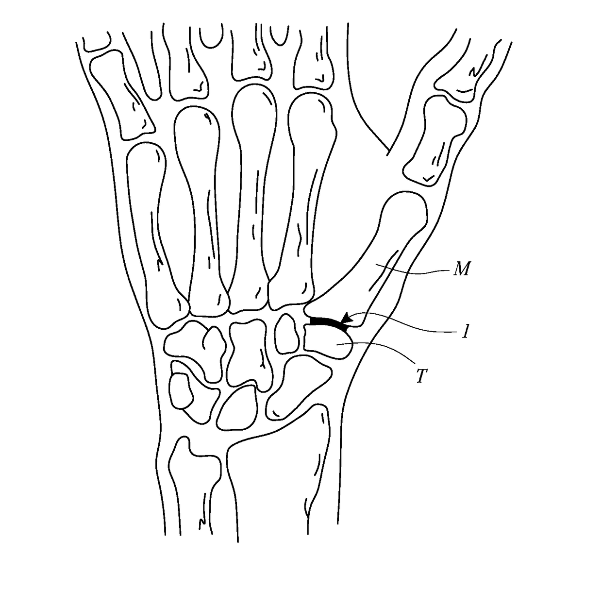
[0017]As used herein, the terms “frontal,”“antero-posterior,” and similar terms are to be understood in their anatomical sense in relation to a patient whose hand is being operated upon. With that in mind, in FIGS. 1 to 5, a trapeziometacarpal implant 1 is shown which is designed to be implanted by interposition in a trapeziometacarpal joint between a trapezium T and a first metacarpal M of a human hand, as is shown by way of example in FIG. 1.

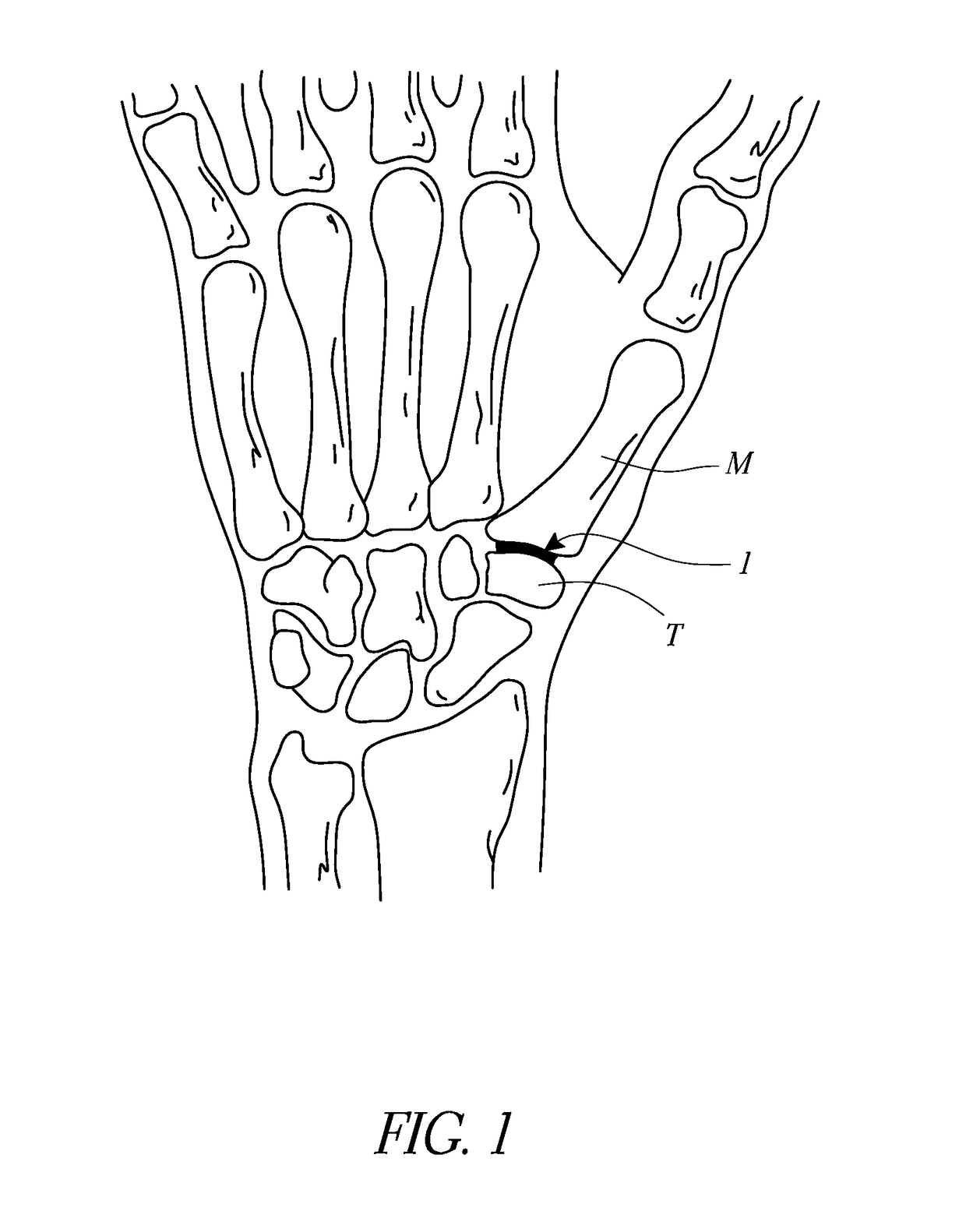
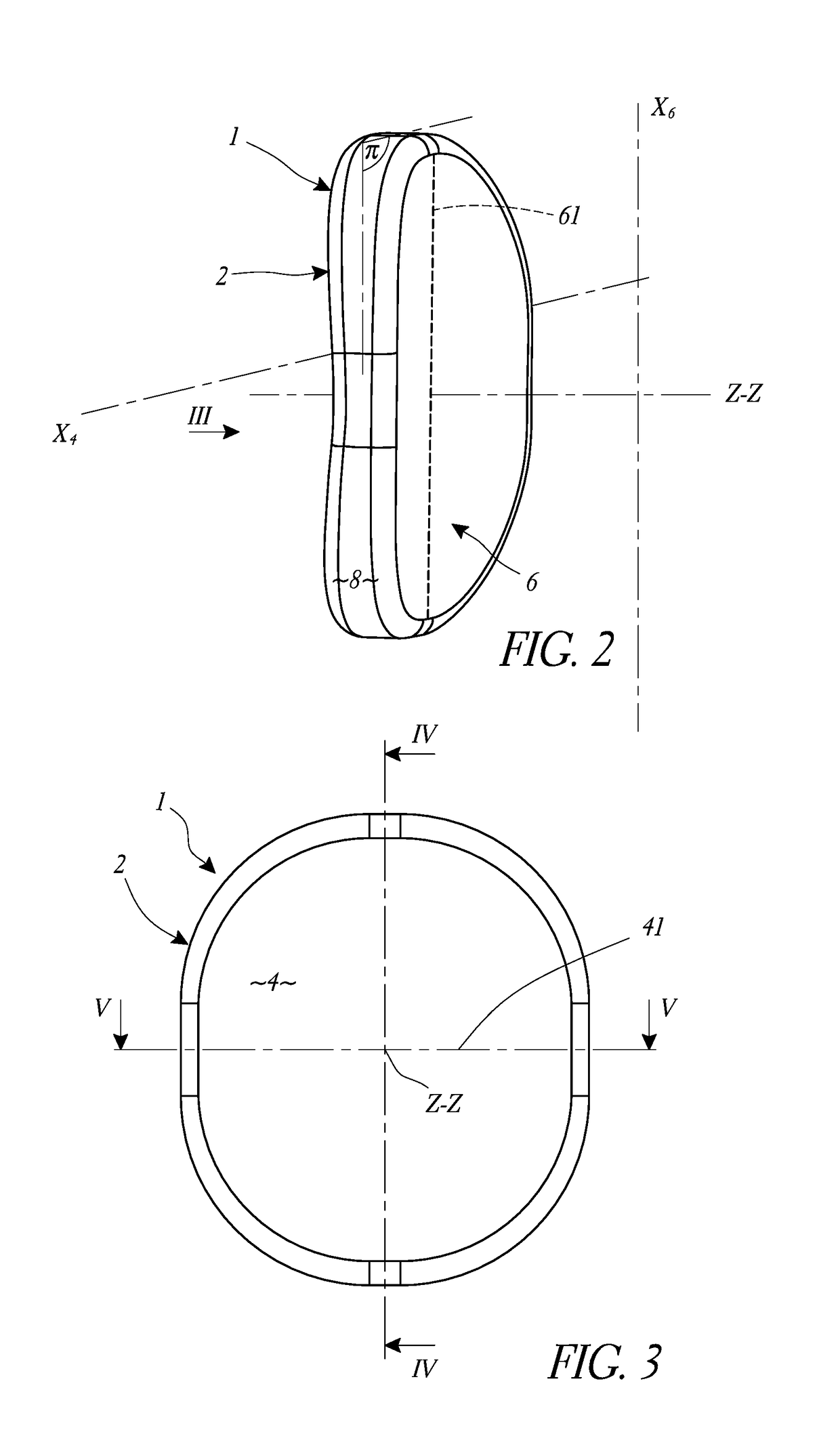
[0018]The implant 1 comprises a generally disk-shaped body 2 centered on a geometric axis Z-Z, also described as a transverse axis. The body 2 delimits a first main surface 4 and a second main surface 6, also referred to as metacarpal and trapezium joint surfaces, respectively, or primary bone contact surfaces, for example. In some embodiments, the first and second main surfaces 4 and 6 are positioned opposite each other on the axis Z-Z and separated from each other by the thickness of the body 2 along the axis Z-Z. The body 2 also includes a ...


PUM

PropertyMeasurementUnit
thicknessaaaaaaaaaa
thicknessaaaaaaaaaa
areaaaaaaaaaaa

Abstract

A trapeziometacarpal joint implant includes a body defining a median plane, a metacarpal joint surface, and a trapezium joint surface. A first central region of the metacarpal joint surface is situated on an opposite side of the median plane from a second central region of the trapezium joint surface. The first and second central regions correspond to profiles of a first axial segment and a second axial segment, respectively. The first and second axial segments are one of a cylinder, a cone and a torus and are centered on a first axis and a second axis, respectively, where the first and second axes, as projected on the median plane, are substantially perpendicular to each other.

Description

INCORPORATION BY REFERENCE TO ANY PRIORITY APPLICATIONS[0001]The present application is a divisional of U.S. patent application Ser. No. 12 / 819,390, filed on Jun. 21, 2010, which claims the benefit of French Patent Application No. FR0954190, filed on Jun. 19, 2009, and entitled “IMPLANT D'ARTICULATION TRAPÉZO-MÉTACARPIENNE,” which is incorporated herein by reference in its entirety for all purposes.BACKGROUND OF THE INVENTION[0002]Trapeziometacarpal prostheses and implants are designed to restore the strength and mobility of the anatomical joint of the thumb, between its metacarpal and the trapezium, when the joint is damaged by a degenerative or inflammatory pathological process. Many trapeziometacarpal prostheses are stem prostheses in which the metacarpal prosthetic component is anchored at one end in the metacarpal by an elongate stem while the other end of the prosthetic component is mounted pivotably either in a prosthetic component attached to the trapezium or in a cavity hol...

Claims


Application Information

Patent Timeline
Patent Type & Authority Patents(United States)
IPC IPC(8): A61F2/42A61F2/30
CPCA61F2/4261A61F2/4241A61F2002/302A61F2002/30153A61F2002/30205A61F2002/30224A61F2002/30301A61F2002/30616A61F2002/30754A61F2002/4258A61F2230/0019A61F2230/0065A61F2230/0067A61F2230/0069A61F2230/0095A61F2310/00173A61F2310/00574
Inventor HASSLER, MICHELBELLEMERE, PHILIPPE
Owner TORNIER SA SAINT ISMIER
Why Eureka
Try Eureka