
Assembly for harnessing a pendulum motion from fluid wave energy for conversion to power

a technology of fluid wave energy and pendulum, which is applied in the direction of mechanical equipment, electric generator control, machines/engines, etc., can solve the problems of nuclear energy requiring the disposal of spent nuclear fuel, polluting the air, and all of the fuel resources are rapidly diminishing

Active Publication Date: 2017-10-03
LI XIAO LIANG
View PDF83 Cites 3 Cited by
  • Summary
  • Abstract
  • Description
  • Claims
  • Application Information

AI Technical Summary

Benefits of technology

The system efficiently converts wave energy into electricity by stabilizing and regulating the pendulum motion, enhancing energy capture and reducing energy loss, while operating reliably in harsh marine conditions.

Problems solved by technology

Burning oil, gas and coal results in polluted air, and all of those fuel resources are rapidly diminishing as the need for electricity has skyrocketed in developed countries.
Further, nuclear energy requires the disposal of spent nuclear fuel, which remains dangerous for centuries.
Wind turbines also have a potentially unlimited power source, the wind, but will also not produce any power when the wind is light.
However, with no practical way to store excess energy, these sources are generally supplemental to a fossil fuel powered energy system.
However, a large amount of energy is consumed in reversing the rotation direction of the motor rotor.
The problem with these energy harnessing assemblies is that they do not magnify the force from the waves, and are not very durable.

Method used


Image

  • Assembly for harnessing a pendulum motion from fluid wave energy for conversion to power
  • Assembly for harnessing a pendulum motion from fluid wave energy for conversion to power
  • Assembly for harnessing a pendulum motion from fluid wave energy for conversion to power

Examples


Embodiment Construction

[0041]The following detailed description is merely exemplary in nature and is not intended to limit the described embodiments or the application and uses of the described embodiments. As used herein, the word “exemplary” or “illustrative” means “serving as an example, instance, or illustration.” Any implementation described herein as “exemplary” or “illustrative” is not necessarily to be construed as preferred or advantageous over other implementations. All of the implementations described below are exemplary implementations provided to enable persons skilled in the art to make or use the embodiments of the disclosure and are not intended to limit the scope of the disclosure, which is defined by the claims. For purposes of description herein, the terms “upper,”“lower,”“left,”“rear,”“right,”“front,”“vertical,”“horizontal,” and derivatives thereof shall relate to the invention as oriented in FIG. 1. Furthermore, there is no intention to be bound by any expressed or implied theory pres...


PUM


Abstract

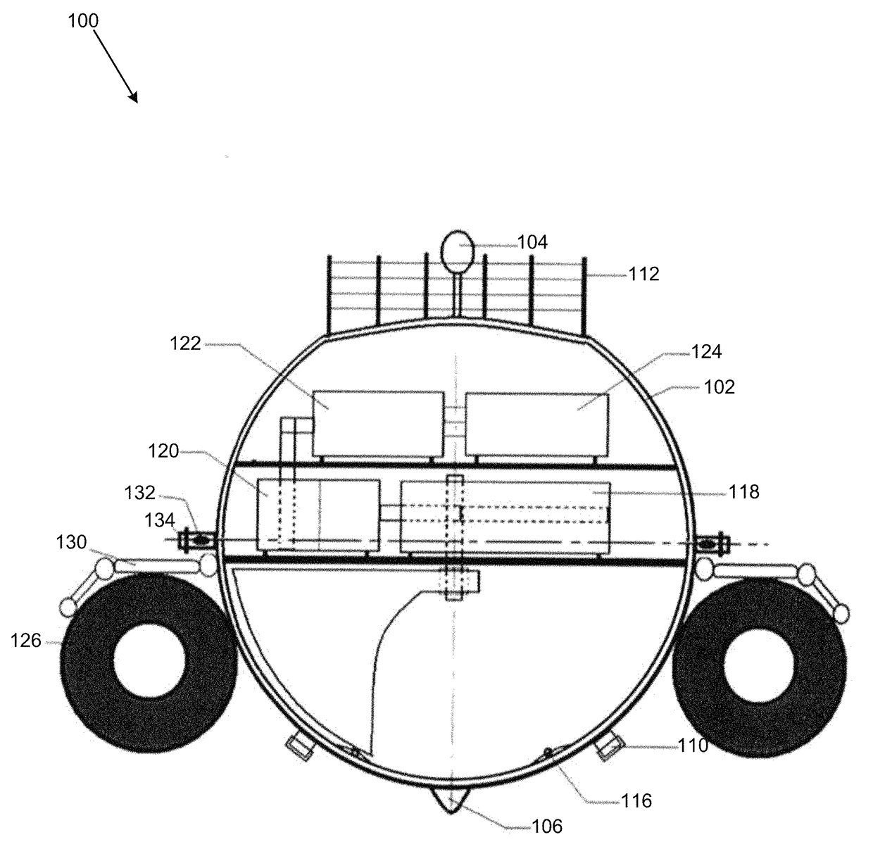
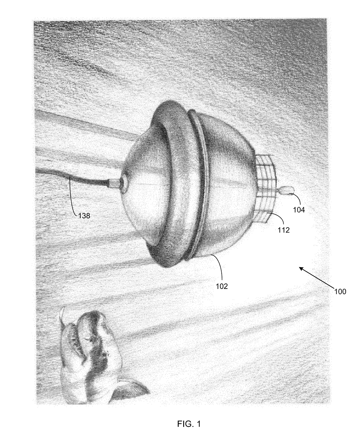
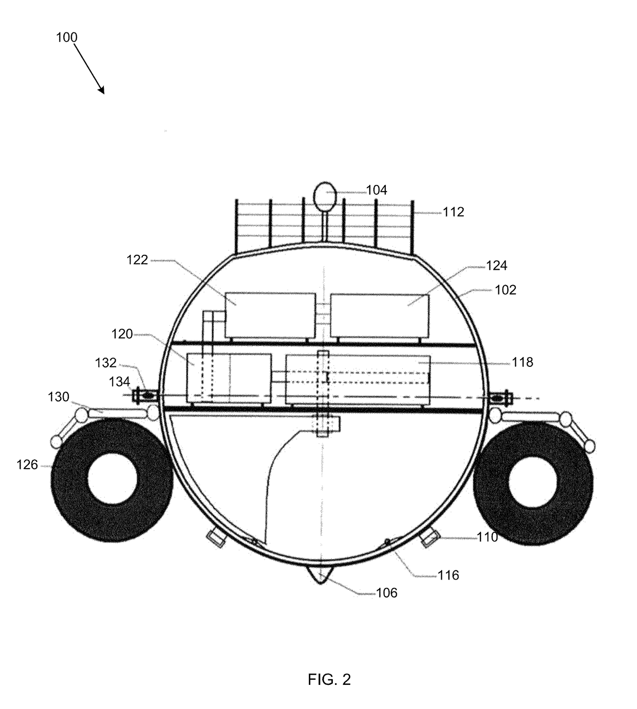
An assembly for harnessing a pendulum motion from fluid wave energy to convert to power. The assembly converts a fluid wave energy into electricity through a pendulum mechanism. The pendulum mechanism makes use of a buoyant sphere that floats in a fluid and absorbs wave energy, such as oscillations, vibrations, and disturbances known in wave energy, while floating in the fluid. A hemispherical pendulum swings in relation to the wave energy. The hemispherical pendulum transmits the swinging motion to an electrical generator for conversion to electricity. The harnessing of wave energy and swinging of the hemispherical pendulum is controlled through various components that balance and stabilize the assembly. The sphere comprises components to help control the irregularities from wave energy on the hemispherical pendulum through a directional guidance member, a velocity regulation member, and a stabilization member. A transmission cable transmits the electricity to a control center on shore.

Description

CROSS REFERENCE OF RELATED APPLICATIONS[0001]This application claims the benefits of U.S. provisional application No. 62 / 214,382, filed Sep. 4, 2015, and entitled DEVICE FOR CONVERTING FLUID WAVE ENERGY TO ELECTRICITY THROUGH A PENDULUM MECHANISM, which provisional application is incorporated by reference herein in its entirety.FIELD OF THE INVENTION[0002]The present invention relates generally to an assembly for harnessing a pendulum motion from fluid wave energy for conversion to power. More so, an assembly is configured to convert fluid wave energy into power through the use of a pendulum mechanism that includes a buoyant sphere that absorbs wave energy while floating in a fluid; whereby the sphere contains a hemispherical pendulum that swings in relation to the wave energy and transmits the swinging motion to an electrical generator for conversion to power; whereby the hemispherical pendulum swings under the control of a directional guidance member, a velocity regulation member,...

Claims


Application Information

Patent Timeline
Patent Type & Authority Patents(United States)
IPC IPC(8): F03B13/10F03B13/12H02P9/04H02K7/18F03B13/20F03B13/18
CPCH02K7/1853F03B13/20H02K7/1892F05B2250/241Y02E10/38Y02E10/30F05B2250/44
Inventor LI, XIAO LIANG
Owner LI XIAO LIANG
Learn More